
Installation Guide


GENERAL FASTENING REQUIREMENTS
Fasteners must be corrosion resistant, galvanized, or stainless steel. Electro-galvanized
are acceptable but may exhibit premature corrosion. James Hardie recommends the
use of quality, hot-dipped galvanized nails. James Hardie is not responsible for the
corrosion resistance of fasteners. Stainless steel fasteners are recommended when
installing James Hardie
®
products near the ocean, large bodies of water, or in very
humid climates.
Manufacturers of ACQ and CA preservative-treated wood recommend spacer materials
or other physical barriers to prevent direct contact of ACQ or CA preservative-treated
wood and aluminum products. Fasteners used to attach HardieTrim Tabs to preserva-
tive-treated wood shall be of hot dipped zinc-coated galvanized steel or stainless steel
and in accordance to 2009 IRC R317.3 or 2009 IBC 2304.9.5
• Consult applicable product evaluation or listing for correct fasteners type and
placement to achieve specified design wind loads.
• NOTE: Published wind loads may not be applicable to all areas where Local Building
Codes have specific jurisdiction. Consult James Hardie Technical Services if you are
unsure of applicable compliance documentation.
• Drive fasteners perpendicular to siding and framing.
• Fastener heads should fit snug against siding (no air space).
• NOTE: Whenever a structural member is present, HardiePlank should be fastened with
even spacing to the structural member. The tables allowing direct to OSB or plywood
should only be used when traditional framing is not available.
HardieSoffit
®
Panels
SF1204 P2/3 04/19
Figure 5
• For wood frame construction a minimum 4d common nails spaced 8 in o.c. at
panel edges and intermediate framing members spaced up to 24 in on center are
suitable in most locations*.
• For conventional 20ga - 16ga steel frame construction a minimum No. 8-18 x
0.323 in HD x 1 in long ribbed bugle screws spaced 6 in o.c. at panel edges and
intermediate framing members spaced up to 24 in on center are suitable in most
locations*.
*Minimum Basic Wind Speed differs by locality. Where specified levels of wind
resistance are required, refer to applicable Building Code Compliance Reports.
FASTENER REQUIREMENTS
Figure 6
Self-adhering
membrane
Step flashing
Housewrap
Drip edge
Kickout
flashing
Self-adhering
eaves membrane
Because of the volume of water that can pour down a sloped roof, one of the most
critical flashing details occurs where a roof intersects a sidewall. The roof must be
flashed with step flashing. Where the roof terminates, install a kickout to deflect
water away from the siding. It is best to install a self-adhering membrane on the
wall before the subfascia and trim boards are nailed in place, and then come back
to install the kickout.
KICKOUT FLASHING
Figure 6, Kickout Flashing To prevent water from dumping behind the siding
and the end of the roof intersection, install a "kickout" as required by IRC code
R905.2.8.3 : “...flashing shall be a min. of 4” high and 4” wide.” James Hardie
recommends the kickout be angled between 100° - 110° to maximize water
deflection
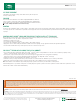
PNEUMATIC FASTENING
James Hardie products can be hand nailed or fastened with a pneumatic tool.
Pneumatic fastening is highly recommended. Set air pressure so that the
fastener is driven snug with the surface of the siding. A flush mount attachment
on the pneumatic tool is recommended. This will help control the depth the nail
is driven. If setting the nail depth proves difficult, choose a setting that under
drives the nail. (Drive under driven nails snug with a smooth faced hammer -
Does not apply for installation to steel framing).
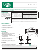
Figure 5
Maintain a minimum 1 in gap between
gutter end caps and siding & trim.
fascia
siding
1 in min.
gutter and end cap
Manufacturers of ACQ and CA preservative-treated wood recommend spacer
materials or other physical barriers to prevent direct contact of ACQ or CA
preservative-treated wood and aluminum products. Fasteners used to attach
HardieTrim Tabs to preservative-treated wood shall be of hot dipped zinc-coated
galvanized steel or stainless steel and in accordance to 2009 IRC R317.3 or 2009
IBC 2304.9.5.”
3/8 in from edge of soffit
keep fasteners
2 in away
from corners
24” o.c. max.
Figure 4
Greater than
12 in Wide Soffit
Figure 3
1 in from end of soffit
3/8 in from edge of soffit
less than or equal to
12 in Wide Soffit
ALUMINUM
CLIPPED
STAPLES
HEAD NAILS
FASTENERS
UNDER
DRIVE
OVER
DRIVE
SLANT
IF, THEN IF, THEN ADDITIONAL NAIL
WOOD
FRAME
HAMMER
FLUSH
REMOVE &
REPLACE
COUNTERSINK
& FILL
STEEL
FRAME
FACE
NAIL
DO NOT DO NOT
DO NOT USE
AL
SNUG FLUSH