
Installation Guide


91
HS11119-P2/4 05/16
* When face nailing to OSB, planks must be no greater than 9 1/4 in. wide and fasteners must be 12 in. o.c. or less.
Laminate sheet to be removed immediately after installation of each course for ColorPlus
®
products.
** Also see General Fastening Requirements; and when considering alternative fastening options refer to James Hardie Technical Bulletin USTB 17 - Fastening Tips for HardiePlank
®
Lap Siding.
**
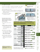
FASTENER REQUIREMENTS
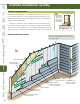
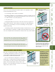
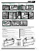
CLEARANCE AND FLASHING REQUIREMENTS
Figure 16
water-resistive
barrier
face nail
3/4 in.-1 in.
24 in.
O.C. max.
stud
1 1/4 in. min.
overlap
min. 1 1/4 in.
overlap
Minimum overlap
for Both Face
and Blind Nailing
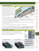
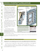
Figure 15
BLIND NAILING
Nails - Wood Framing
• Siding nail (0.09 in. shank x 0.221 in. HD x 2 in. long)
• 11ga. roofing nail (0.121 in. shank x 0.371 in. HD x 1.25 in. long)
Screws - Steel Framing
• Ribbed Wafer-head or equivalent (No. 8 x 1 1/4 in. long x 0.375 in. HD) Screws
must penetrate 3 threads into metal framing.
Nails - Steel Framing
• ET & F Panelfast
®
nails or equivalent (0.10 in. shank x 0.313 in. HD x 1-1/2 in.
long)
Nails must penetrate minimum 1/4 in. into metal framing.
OSB minimum 7/16 in.
• 11ga. roofing nail (0.121 in. shank x 0.371 in. HD x 1.75 in. long)
• Ribbed Wafer-head or equivalent (No. 8 x 1 5/8 in. long x 0.375 in. HD).
FACE NAILING
Nails - Wood Framing
• 6d (0.113 in. shank x 0.267 in. HD x 2 in. long)
• Siding nail (0.09 in. shank x 0.221 in. HD x 2 in. long)
Screws - Steel Framing
• Ribbed Bugle-head or equivalent (No. 8-18 x 1-5/8 in. long x
0.323 in. HD) Screws must penetrate 3 threads into metal framing.
Nails - Steel Framing
• ET & F pin or equivalent (0.10 in. shank x 0.25 in. HD x 1-1/2 in. long)
Nails must penetrate minimum 1/4 in. into metal framing.
OSB minimum 7/16 in.
• Siding nail (0.09 in. shank x 0.221 in. HD x 1-1/2 in. long)*
Nail Line
1 1/4” min.
Overlap
Blind Nail
24”
O.C. max
Water Resistive
Barrier
Stud
Blind Nailing is the preferred method of installation for HardiePlank
®
lap siding products. Face nailing should only be used where required by code for high wind
areas and must not be used in conjunction with Blind nailing (Please see JH Tech bulletin 17 for exemption when doing a repair). Pin-backed corners may be
done for aesthetic purposes Only. Pin-backs shall be done with finish nails only, and are not a substitute for blind or face nailing.
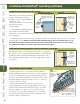
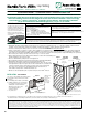
Figure 3
Roof to Wall
Figure 4
Horizontal Flashing
Figure 5
Kickout Flashing
Figure 6
Slabs, Path, Steps to Siding
Figure 7
Deck to Wall
Figure 8
Ground to Siding
Figure 10
Sheltered Areas
Figure 9
Gutter to Siding
Figure 12
Drip Edge
Figure 13
Block Penetration
(Recommended in HZ10)
Figure 14
Valley/Shingle Extension
Figure 11
Mortar/Masonry
Min.
1 in.-2 in.
Min.
1 in.-2 in.
6 in.
1
in.
Z-Flashing
Z-Flashing
Z-Flashing
Min.
1 in.-2 in.
Min. ¼ in.
Min. ¼ in.
Do not caulk
Min. ¼ in.
Min. ½ in.
Z-Flashing
Extend shingles
at least 1 in. out
from the fascia
when gutters
are present
Z-Flashing
L-Flashing
As required
by IRC code
min 4 in. x 4 in.
Min. ¼ in.
Do not caulk