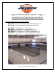
--- Jaypro Retractable Practice Cages --Installation and Operating Instructions Applicable Jaypro Part Numbers / Cage Models: BBC-700B = Ceiling Suspended Retractable Baseball Batting Cage BBC-700M = Ceiling Suspended Retractable Multi Sport Cage BBC-UBKIT = Installation Kit A – Direct Attached BBC-UP5KIT = Installation Kit B – Spanning Parallel <=5’ BBC-KIT58 = Installation Kit C – Spanning Parallel >5’ & <=8’ BBC-PERPKIT = Installation Kit D – Spanning Perpendicular <=8’ BBC-RIGKIT = Installation Kit E –
Important Notes Caution! This cage system is capable of lifting upwards of 1000 lbs of retractable cage frames and nets. However, injury and / or death can result if equipment is used in an unsafe manner. Do not lift more than one 12’ x 70’ cage. Follow all warning signs and labels on equipment. Inspect all equipment before each use. Do not operate equipment if any cables are frayed or bent, or any wires have been damaged.
Only licensed electricians are permitted to provide power to the key switch, and to and from the winch. Authorized installation personnel may provide temporary wiring only for the purpose of testing equipment during the installation of the product. Call Jaypro Sports Equipment at 1-800-243-0533 during regular business hours for any technical support questions or issues. Refer to Cage model number listed above when talking to customer service personnel. www.jaypro.
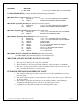
Call Jaypro for pricing and scheduling of a field maintenance visit from one of our highly trained specialists if you are unwilling or unable to perform the regular maintenance yourself. Jaypro recommends that the Cage system be thoroughly inspected at least every year by a trained specialist. Call Jaypro or your dealer to arrange for servicing. Jaypro Sports Equipment Phone #: 1-800-243-0533 Website: www.jaypro.com Operating Instructions 1. Key Switch Operation a.
regularly and if there is any sign of wear on the visible internal components a qualified service technician should be called in for further study. b. Inspect all attachment hardware for both the winch and the cable. Retighten or replace all hardware as necessary. 4. Service Plan & On-Site Maintenance Inspection a. A thorough yearly inspection is recommended for entire system of hoists, cables, wiring, etc.
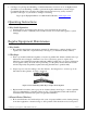
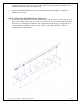
INSTALLATION PROCEDURES Important Note: The following installation procedures show the installation of a batting cage being directly attached to a single I-beam or bar joist, using the BBC-UBKIT mounting kit. Alternate mounting kits are available to attach cages between bar joists (BBC-UP5KIT, BBC-KIT58) and perpendicular to bar joists (BBC-PERPKIT).
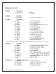
ITEMS AND COUNTS PACKAGE 1 PACKAGE 2 TW-1200X-3C (1) TW-1200X-3C (1) KS-13 WINCH KEY SWICH BBC-700DT (7) DRIVEPIPE-B 2-3/8" OD GALV TUBES 135.
PACKAGE 7 BBC-700M (1) BBC-700M 12' X 10' X 70' TUNNEL #252 3/4" SQ NETTING CAGE SUPPORT KITS (Contains Attachment Kit and Support Structure) BBC-UBKIT (Direct Attached) Purchased Separately (9) SR5239-36 1 5/8 x 1 5/8 x 36 in SINGLE STRUT CHANNEL (18) HM6157 SINGLE STRUT BEAM CLAMP ASSEMBLY BBC-UP5KIT (Spanning Parallel 5 ft. or less) Purchased Separately (9) SR5239-96 1 5/8 x 1 5/8 x 96 in SINGLE STRUT CHANNEL (36) HM6157 SINGLE STRUT BEAM CLAMP ASSEMBLY BBC-KIT58 (Spanning Parallel 5 ft.
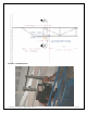
FIGURE 1- MOTOR REFERENCE POINT INSTALL MOTOR ATTACHMENT STRUT AND MOTOR ASSEMBLY. 1. 2 pieces of Unistrut that is 11” c/c are attached to the beam with unistrut clamps at a location of the first piece a minimum of 14” outside the frame perimeter away from the motor reference point. 2. Loosely assemble the motor assembly and hoist it into position. 3. Attach the motor assembly to the motor strut and establish the drive pipe centerline Above Finished Floor, (AFF). 4.
FIGURE 2 - MOTOR INSTALL © 2010 Jaypro Sports Equipment BBC-700B-M 02-08-2012 10 of 24
FIGURE 3 - MOTOR ASSEMBLY INSTALL FIRST DRIVE PIPE CARRIER STRUT AND ASSEMBLY. 1. The next attachment is that of the first Drive Pipe carrier assembly to unistrut that is located 1’ from the motor reference point to be located within the perimeter of the cage. 2. Attach this piece of strut to the beam with usistrut beam clamps. 3. Attach a loosely assembled Drive Pipe Carrier Assembly, (DPC-A), to the strut. 4. Establish the required Drive Pipe Centerline AFF for the carrier. 5.
FIGURE 4 - FIRST DPC © 2010 Jaypro Sports Equipment BBC-700B-M 02-08-2012 12 of 24
FIGURE 5 - SECTION B-B INSTALL THE FIRST SEGMENT OF DRIVE PIPE 1. Insert the Swaged end of one section of drive pipe into the winch drum and push towards the first DCP-A. Pipe may be inserted opposite direction if clearance is an issue. 2. Continue to insert the drive pipe segment through the DPC-A and continue the edge of the pipe to end 27-3/4” beyond the center of the DPC-A. 3. Temporarily secure the drive pipe section to the winch with Duct Tape to prevent it moving unexpectedly.
FIGURE 6- DRIVE PIPE SEGMENT INSTALL A PAIR OF CABLE GUIDES ONTO THE DRIVE PIPE. 1. Slip a pair of cable guides on to the drive pipe. 2. Position the cable guides with the large discs next to each other. 3. DO NOT tighten these to the drive pipe at this point.
INSTALL THE SECOND DRIVE PIPE CARRIER STRUT AND ASSEMBLY. 1. You will continue to work away from the motor reference point. 2. The strut for the second drive pipe carrier is installed with strut beam clamps at a location that is 11’ from the first drive pipe carrier location. 3. Loosely install a DPC-A to that strut and adjust for Drive Pipe Center line AFF. 4. Secure all nuts to mount the assembly to the strut. FIGURE 7 - SECOND DPC INSTALL THE SECOND DRIVE PIPE SEGMENT TO THE FIRST DRIVE PIPE SEGMENT.
i. Drill thru the swaged end of the first drive pipe segment by using the pre-drilled holes on the non swaged end of the second drive pipe as alignment. ii.
INSTALL A PAIR OF CABLE GUIDES ONTO THE DRIVE PIPE. 1. Slip a pair of cable guides on to the drive pipe. 2. Position the cable guides with the large discs next to each other. 3. DO NOT tighten these to the drive pipe at this point. CONTINUE DPC-A STRUT, ASSEMBLY, DRIVE PIPE SEGMENTS, SPLICES AND CABLE GUIDES FOR THE REMAINING PARTS. 1. Assure that you are maintaining level drive pipe center line AFF throughout the process. 2. Each remaining DPC-A should be 11’ from the last.
TRIM ANY EXCESS THREAD ROD THAT MAY EXIST. POSITION AND SECURE THE CABLE GUIDE PAIRS AND HOIST CABLES. 1. Each cable guide pair should be located between a drive pipe carrier and a drive pipe splice. IT IS CRITICAL THAT THE GUIDES BE DIRECTLY ABOVE THE HOIST CABLE LOCATIONS. THE FIRST GUIDE IS 2’ FROM THE FRAME EDGE AND SUBSEQUENT GUIDES ARE 11’ C/C. 2. The cable guide pairs should be positioned to allow 2” of space between the discs. 3.
ASSEMBLE THE CAGE FRAME. 1. Protect the floor of the building by inserting wood blocks under all fame segments and fittings. While drilling or screwing frame together, protect the floor where you are working with a scrap piece of plywood. This will protect the floor surface should a drill accidentally slip from it’s intended direction. 2. Assemble in final position by aligning the motor reference point to the centerline of the cage’s 12’ on the ground. 3.
Check that all burrs have been removed from the inside of the BBC-EL and BBC-T prior to assembly. These fitting should move freely on their pipes. ATTACH THE ANCHORING EYE BOLTS TO THE FRAME AND SECURE 1. There are 21 connection points on the cage 2. Each connection point is a 3/8” x 5” EYE Bolt with washers and a Nylon lock nut. 3. Note that you will be required to drill through the T fitting at the end hoist cable locations. ATTACH THE HOIST CABLES TO THE CENTER EYE BOLTS.
ELECTRIFY THE WINCH. 1. A licensed electrician should perform the final electrical hook ups. HOIST THE FRAME OFF THE GROUND TO APROX 4 ½- 5’ AFF ATTACH THE NET TO THE FRAME WITH THE VELCRO. 1. Two sided hook and loop tape is provided in a roll. 2. Cut the tape into 9” strips to secure the net to the frame. 3. The 9” tape section is wraped around the frame pipe and through the net and secured to itself. 4. Strips should be placed 18-24” center to center along the sides and cross members of the cage frame.
ROLL THE NET ONTO THE TOP OF THE FRAME.
SET THE UPPER LIMIT SWITCH OF THE WINCH. 1. It is recommended that the upper limit be set with a margin of safety. The highest cable clamp on the hoist cable should come to rest between 8 and 12” below the drive pipe. LOWER THE FRAME AND ESTABLISH AN ADJUSTED LOWER LIMIT APROX 3’ AFF UNROLL THE NET FROM THE TOP OF THE FRAME TO HANG FREELY RAISE THE FRAME TO 10’ AFF 1. THIS SHOULD LEAVE APROX 1’ OF NET ON THE GROUND AND IS DESIREABLE IF SO EQUIPPED. INSTALL A TARGET TO THE BATTERS END OF THE NET. 1.
--- Jaypro Batting Cage System --Installation Record Installer - please provide the following information and fax a copy to (860) 440-0628: Installer Name: _______________________________________ Phone #: _______________________________________ Date: _______________________________________ G. C.