
Manual

© 2010 Jaypro Sports Equipment BBC-700B-M 02-08-2012
8of 24
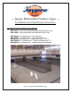
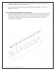
PACKAGE 7 BBC-700M
(1) BBC-700M 12' X 10' X 70' TUNNEL #252 3/4" SQ NETTING
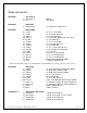
CAGE SUPPORT KITS (Contains Attachment Kit and Support Structure)
BBC-UBKIT (Direct Attached) Purchased Separately
(9) SR5239-36 1 5/8 x 1 5/8 x 36 in SINGLE STRUT CHANNEL
(18) HM6157 SINGLE STRUT BEAM CLAMP ASSEMBLY
BBC-UP5KIT (Spanning Parallel 5 ft. or less) Purchased Separately
(9) SR5239-96 1 5/8 x 1 5/8 x 96 in SINGLE STRUT CHANNEL
(36) HM6157 SINGLE STRUT BEAM CLAMP ASSEMBLY
BBC-KIT58 (Spanning Parallel 5 ft. to 8 ft) Purchased Separately
(9) SR5243-120 1 5/8 x 3 1/4 x 120 in DOUBLE STRUT CHANNEL
(36) HM6159 DOUBLE STRUT BEAM CLAMPS
BBC-PERPKIT
(Spanning Perpendicular) Purchased Separately
(2) SR5239-24 1 5/8 x 1 5/8 x 24 SINGLE STRUT CHANNEL
(8) SR5243-240 1 5/8 x 3 1/4 x 240 in DOUBLE STRUT CHANNEL
(6) HM6222 4 HOLE PLATE
(32) HM6159 BEAM CLAMPS
(24) HS5133 1/2 -13 x 1 1/4 in HEX HEAD CAP SCREW
(4) HW2050 3/8 FLAT WASHER
(4) HS 286 3/8-16 x 1 in HEX HEAD CAP SCREW
(4) HM6158 3/8-16 STRUT NUT
(24) HM6134 1/2 -13 STRUT NUT
BBC-RIGKIT
(Peaked or Rigid Frame Buildings) Purchased Separately
(See BBC-RIGKIT support drawing package for detailed parts lists)
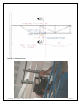
MEASURE AND ESTABLISH LOCATION OF CAGE.
1. The cage is 12’ Wide by 70’ long once assembled.
2. There should be a clear area around the perimeter of the cage that is 3’ minimum.
3. The motor of the cage should be located outside the frame to allow for service to the
motor in either the retracted or down position.
ESTABLISH THE MOTOR REFERENCE POINT.
1. The assembly of the cage and drive system is based on the establishment of a motor
reference point.
2. The motor reference point is on the center line of the 12’ side of the cage on either end
of the cage frame.
3. The reference point must be transferred to the ceiling structure of the building to
establish the attachment points for the motor and drive pipe carriers.
4. A plumb laser is the preferred method for achieving this location.