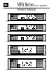
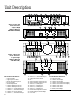
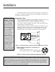
MPA Series Power Amplifiers Owner’s Manual Clip MPA275 Professional Amplifier Clip -10dB -10dB -20dB Protect -20dB Signal Present Power Signal Present 10 12 8 18 4 24 2 1-CHANNEL-2 0 6 18 4 24 8 14 6 48 10 12 14 2 48 0 MPA275 Clip MPA400 Professional Amplifier Clip -10dB -10dB -20dB Protect -20dB Signal Present Power Signal Present 12 10 8 12 14 18 6 4 24 2 48 8 18 4 24 10 14 6 1-CHANNEL-2 0 2 48 0 MPA400 Clip MPA600 Professional Amplifier
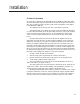
Cautions Sicherheitsvorschriften Rack Mounting Precautions Sicherheitsvorschriften für den Einbau in ein Gestell To avoid damage to the amplifier mounting ears and/or rack rails, the amplifier must be supported at all four corners when used in portable racks. Um Schäden auf den Befestigungsleisten des Verstärkers und/oder den Gestellschienen zu vermeiden, muß der Verstärker beim Einbau in ein tragbares Gestell an allen vier Ecken gestützt werden.
Table of Contents Cautions .................................................................................................................1 Unit Description ....................................................................................................3 General Information ....................................................................................................3 Open Input Architecture™ Slots .................................................................................
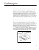
Unit Description The MPA275, MPA400, MPA600, MPA750 and MPA1100 are high-efficiency professional power amplifiers, with two independent channels, respectively capable of delivering 275, 400, 600, 750 and 1100 watts into a four ohm load (per channel), and substantially more power into lower impedance loads. Semi-toroidal power transformers (one per channel in the MPA750 and MPA1100) are mounted in each front corner, as close as possible to the rack ears and rails. The rear panels are 16.
Unit Description 1 2 4 5 3 14 15 17 CHANNEL 2 19 – BRIDGED MONO 16 CHANNEL 1 + – GND – + P1 BRIDGE + PARALLEL INPUT GND P2 STEREO OUTPUT OUTPUT GND P2 CH 1 P1 DUAL CHANNEL OUTPUT CONNECTOR SENSITIVITY 1 VOLT IMPEDANCE 20K BAL 10K UNBAL Figure 2.
Installation Inputs Balanced input connections are available via barrier strip or XLR connectors. The unit is shipped with pin 2 high (see subsequent instructions to change polarity). As usual, for unbalanced inputs, the unused terminal should be terminated to ground (the negative input terminals on the barrier strip are located adjacent to the ground terminal for this purpose). Input sensitivity is 1 Vrms, and impedance is 20 kilohm balanced, 10 kilohm unbalanced, as is typical of JBL amplifiers.
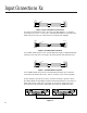
Input Connections Xx Output (Source) Shield MPA Input 1 + 2 Unbalanced Balanced 3 Figure 5. Typical Unbalanced Connection To connect an unbalanced source to the input of an MPA amplifier, “+” should be connected to pin 2, and “-” to pin 3 The “-” terminal should also be connected to the shield at the source only. Pin 1 should not be connected at the amplifier. Output (Source) MPA Input Shield 1 1 2 2 3 3 Balanced Balanced Figure 6.
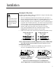
Installation Changing the XLR polarity The MPA275, MPA400, MPA600, MPA750 and MPA1100 are shipped with XLR polarity set at pin 2 high. To convert to pin 3 high: 1. 2. 3. 4. 5. Remove the Standard Input Module and input ribbon cable. (See Figure 1). Find the soldered jumpers W303, W304 (Ch 1) and W403, W404 (Ch 2), located behind each XLR jack. These are soldered in positions marked “PIN 2 HI”. Desolder each jumper, and move it lengthwise 0.
Installation With paralleled inputs, the signal may be looped through (or “daisy-chained”) by going in one channel’s inputs and out the other. The amplifier Gain settings will not affect the level at the input jacks. BRIDGED-MONO MODE CAUTION: Output voltages up to 200 volts rms are available between the MPA1100’s bridged terminals (140 volts into an 8 ohm load). Even on the MPA600, 150 volts rms are available between the bridged terminals (103 volts into an 8 ohm load).
Installation AC Power Connection AC Connection is made through a standard Schuko or NEMA grounded plug. While all models meet Safety Agency requirements for current consumption of less than 12 amp, 120 Vac during “normal” operation, peak current consumption can be higher on the MPA1100 or MPA750. The amplifiers can be wired for 100, 120, or 220–240 Vac, 50–60 Hz. Some background on AC ratings is necessary to fully understand the limitations on current draw.
Operation Operation With 110 VAC, 60 Hz Power Mains 2 CH Load Max Power AC Current Model (Ohms) (Midband) Full Power A A A A A A A A A A A A A A A 10.2A 16.0 A 23.0 A 9.6A 14.4 A 21.0 A 8.4 A 13.5 A 15.2 A 6.6 A 9.6 A 13.2 A 5.4 A 7.2 A 11.2 A 5.4 7.8 11.4 4.6 6.4 10.0 3.4 5.4 8.0 2.6 4.6 5.4 3.6 5.2 7.0 A A A A A A A A A A A A A A A Operation With 115 VAC, 60 Hz Power Mains 8+8 770 x 2 24.0 MPA1100 4+4 1100 x 2 39.0 2+2 1400 x 2 56.0 8+8 510 x 2 18.6 MPA750 4+4 760 x 2 30.0 2+2 1000 x 2 39.
Operation Operation With 220 VAC, 50 Hz Power Mains 2 CH Load Max Power AC Current Model (Ohms) (Midband) Full Power A A A A A A A A A A A A A A A 5.1A 8.0 A 11.5 A 4.8A 7.2 A 10.5 A 4.2 A 6.5 A 7.6 A 3.3 A 4.8 A 6.6 A 2.7 A 3.6 A 5.6 A 2.7 3.9 5.7 2.3 3.2 5.0 1.7 2.7 4.0 1.3 2.3 2.7 1.8 2.6 3.5 A A A A A A A A A A A A A A A Operation With 230 VAC, 50 Hz Power Mains 8+8 770 x 2 12.0 MPA1100 4+4 1100 x 2 19.5 2+2 1400 x 2 28.0 8+8 510 x 2 9.3 MPA750 4+4 760 x 2 15.0 2+2 1000 x 2 19.7 8+8 425 x 2 7.
Operation Controls The front-mounted Gain controls have 11 detents for easy matching of levels. The Gain scale shows dB of attenuation from full gain, with positions for 0 (full), -2, -4, -6, -8, -10, -12, -14, 18, -24, and ∞ (full off). Attenuation is accurate within 1 dB (down to -14 dB). Gain Control Lockout Provided with each amplifier are two lockout knob caps. Carefully remove the Gain control knob (A), as shown in Figure 9. Cover the opening by snapping in the lockout knob cap (B).
Operation NO SIGNAL ON/OFF MUTING Clip Clip -10dB -10dB -20dB Protect -20dB Protect Signal Present Power Signal Present Power SIGNAL PRESENT (-30 dB) CLIP is illuminated at full brightness when the output is muted (PROTECT LED is on, too).
Operation Maximum Long-Term Output Power In most cases, the desired sound level can be obtained without using the full power output of the amplifier. The level displays are then used to confirm that both channels are working as desired. If the amplifier is operated at extreme power levels, it may overheat or the speakers may be damaged.
Operation extended somewhat, and the turn-off muting has been quickened, to ensure muting even of poorly designed preceding components. On/off muting is equally effective whether the amplifier is turned off with its own switch or with a remote switch. Inrush current is limited by an NTC resistor (Negative Temperature Coefficient) which starts at a high resistance and then diminishes after turn-on to avoid loss of power.
Specifications General Specifications DISTORTION SMPTE-IM, less than 0.05 % FREQUENCY RESPONSE 20 Hz to 20 kHz, ±0.1 dB 8 Hz to 100 kHz, +0/-3 dB DAMPING FACTOR DYNAMIC HEADROOM NOISE SENSITIVITY VOLTAGE GAIN INPUT IMPEDANCE CONTROLS INDICATORS (each channel) CONNECTORS (each chan.
Specifications Load & Measure60 Hz AC ment Conditions Power Mains Output RMS Power in Watts MPA1100 8 ohms/channel 20 Hz – 20 kHz 0.1% THD 110 VAC 115 VAC 120 VAC 8 ohms/channel 20 Hz – 15 kHz * 0.1% THD 110 VAC 115 VAC 120 VAC 4 ohms/channel 20 Hz – 20 kHz 0.1% THD 110 VAC 115 VAC 120 VAC 4 ohms/channel 20 Hz – 15 kHz * 0.
Specifications Load & Measure50 Hz AC ment Conditions Power Mains Output RMS Power in Watts MPA1100 8 ohms/channel 20 Hz – 20 kHz 0.1% THD 220 VAC 230 VAC 240 VAC 8 ohms/channel 20 Hz – 15 kHz * 0.1% THD 220 VAC 230 VAC 240 VAC 4 ohms/channel 20 Hz – 20 kHz 0.1% THD 220 VAC 230 VAC 240 VAC 4 ohms/channel 20 Hz – 15 kHz * 0.
Troubleshooting Channel will not come out of muting: A. B. If reducing Gain to zero does not release muting, the channel is defective or overheated (see below). If reducing Gain releases the muting, advance Gain slowly while watching the LEVEL displays (in case there is an abnormal signal which could blow the speakers). No sound is heard: A. B. C. D. Is the channel in muting? (PROTECT is bright, see below).
Troubleshooting Overheating: A. If ventilation is blocked, or if the amplifier is overdriven into low impedance loads, it can overheat. The thermal protection system’s normal response to rising temperatures is as follows: 25–50° C: 50–60° C: 75° C: 85° C: 90° C: 20 Fan runs on low speed. Fan Speed rises gradually from slow to full. PROTECT LED starts flashing. PROTECT flash rate increases, and CLIP starts to glow steadily. The limiter will begin to reduce amplifier gain, up to 15 dB.
For Further Assistance General information or Technical Assistance For more information on JBL products, including these power amplifiers, contact your nearest JBL professional products dealer or the JBL factory at the address below. Repairs Please do not ship your amplifier(s) to JBL or a JBL authorized repair facility without prior authorization. You may obtain that authorization by contacting the factory or repair facility directly.
JBL Incorporated 8500 Balboa Boulevard Northridge, California 91329USA A Harman International Company Part No.