
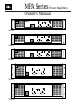
Instruction Manual

2
Cautions .................................................................................................................1
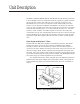
Unit Description ....................................................................................................3
General Information....................................................................................................3
Open Input Architecture™ Slots.................................................................................3
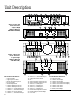
Feature Identification...................................................................................................4
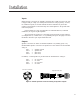
Installation.............................................................................................................5
Inputs ...........................................................................................................................5
Outputs ........................................................................................................................5
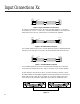
Input Connections.......................................................................................................6
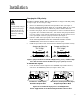
Changing XLR Polarity.................................................................................................7
To Parallel the Inputs..................................................................................................7
Bridged Mono Mode ...................................................................................................8
AC Power Connection.................................................................................................9
Operation.............................................................................................................10
Controls......................................................................................................................12
Gain Control Lockout................................................................................................12
Displays......................................................................................................................12
Typical Power Up, Operation, Power Down Behavior...........................................12
Maximum Long-Term Output Power........................................................................14
Protection Circuits......................................................................................................14
Specifications.......................................................................................................16
Power Output Ratings...............................................................................................17
Troubleshooting ..................................................................................................19
Illustrations
Figure 1. Open Input Architecture Slots.....................................................................3
Figure 2. Rear and Front Views of 2-Space High Amplifiers ....................................4
Figure 3. Rear and Front Views of 3-Space High Amplifiers ....................................4
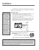
Figure 4. Neutrik Speakon Connector Wiring for Speaker Outputs.........................5
Figure 5. Typical Unbalanced Connection.................................................................6
Figure 6. Portable Balanced System...........................................................................6
Figure 7. Installed Balanced System...........................................................................6
Figure 8. Ground Bus Connection..............................................................................6
Figure 9. Jumper Positions for XLR Polarity Reversal................................................7
Figure 10. Switch Settings for Bridged Mono Operation...........................................7
Figure 11. Connection Options of Speaker Load for Bridged Mono ......................8
Figure 12. Speakon Connection Details for Bridged Mono Operation. ...................8
Figure 13. Gain Control Lockout...............................................................................12
Figure 14. LED Displays During Normal Operation................................................13
Figure 15. LED Displays During Abnormal Operating Conditions .........................13
Tables
Table 1. JBL MPA Series AC Power Consumption
versus Load Impedance With 110, 115 & 120 V Mains ..............................9
Table 2. JBL MPA Series AC Power Consumption
versus Load Impedance With 220, 230 & 240 V Mains.............................10
Table 3. LED Display Operation...............................................................................11
Table 4. Output Ratings With 110, 115 and 120 V Mains........................................16
Table 5. Output Ratings With 110, 115 and 120 V Mains........................................17
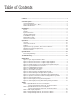
Table of Contents