
Instruction Manual

Xx
6
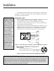
Input Connections
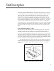
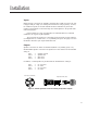
Figure 5. Typical Unbalanced Connection
To connect an unbalanced source to the input of an MPA amplifier, “+” should be
connected to pin 2, and “-” to pin 3 The “-” terminal should also be connected to the
shield at the source only. Pin 1 should not be connected at the amplifier.
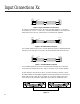
Figure 6. Portable Balanced System
In a portable system using a source unit with balanced outputs, a standard XLR cable
wired pin to pin (with pin 1 connected to the shield at both ends) should be used.
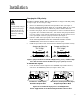
Figure 7. Installed Balanced System
In an installed system using a source unit with balanced outputs, pin 1 should be
connected to the shield at the source, with no connection to pin 1 at the amplifier.
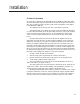
If, after wiring the input as shown above, any hum or buzzing is present, connect
the GND terminals of all amplifiers together. This bus should then be connected to a
stable earth ground. It may also be necessary to connect the chassis of the input
source device to the ground bus, particularly when using an unbalanced source.
+
Output
(Source)
Unbalanced
1
2
3
MPA Input
Balanced
Shield
1
2
3
Output
(Source)
Balanced
1
2
3
MPA Input
Balanced
Shield
1
2
3
Output
(Source)
Balanced
1
2
3
MPA Input
Balanced
Shield
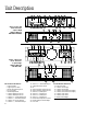
SENSITIVITY
1 VOLT
IMPEDANCE
20K BAL
10K UNBAL
GND
P1
P3
PARALLEL
STEREO
BRIDGE
P2
CHANNEL 1
INPUT
GND
+– –+
GND
P1
P3
P2
CHANNEL 2
SENSITIVITY
1 VOLT
IMPEDANCE
20K BAL
10K UNBAL
GND
P1
P3
PARALLEL
STEREO
BRIDGE
P2
CHANNEL 1
INPUT
GND
+– –+
GND
P1
P3
P2
CHANNEL 2
Figure 8.