
Instruction Manual

7
Changing the XLR polarity
The MPA275, MPA400, MPA600, MPA750 and MPA1100 are shipped with XLR polarity
set at pin 2 high. To convert to pin 3 high:
1. Remove the Standard Input Module and input ribbon cable. (See Figure 1).
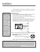
2. Find the soldered jumpers W303, W304 (Ch 1) and W403, W404 (Ch 2), located
behind each XLR jack. These are soldered in positions marked “PIN 2 HI”.
3. Desolder each jumper, and move it lengthwise 0.2 inches to its alternate mount-
ing position (the end marked “PIN 3 HI”), and resolder. Each jumper should fit
in its new position evenly without changing its length. All four must be moved
or the input signal will not be properly connected. (See Figure 5).
4. Label the outside of the Input panel to show that pin 3 is now High.
NOTE: THIS ADJUSTMENT DOES NOT ALTER THE POLARITY OF THE
BARRIER STRIP, which remains as marked on the rear panel.
5. Install the input ribbon cable and remount the Standard Input Module securely.
To Parallel the Inputs
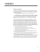
1. Locate the selector switch adjacent to the CHANNEL 1 input XLR connector ,
and set it to the PARALLEL position (see Figure 6 below, left).
Installation
W303
W304
XLR POLARITY
PIN 2 HI PIN 3 HI
W303
W304
XLR POLARITY
PIN 2 HI PIN 3 HI
Jumper positions for
“Pin 3 High”
Jumper positions for
“Pin 2 High”
Figure 9. Jumper Positions for XLR Pin 2 High (factory preset), and Pin 3 High.
Note: Both channels must be modified for proper polarity reversal.
Figure 10. To Parallel the Input Jacks or for Bridged Mono,
Set the Toggle Switch on the Standard Input Module as Shown Here.
GND
P1
P3
PARALLEL
STEREO
BRIDGE
P2
CHANNEL 1
+
GND
P1
P3
PARALLEL
STEREO
BRIDGE
P2
CHANNEL 1
+
Parallel CH 1 & CH 2 Inputs,
Dual Mono Outputs Mode
Shared CH 1 (Polarity Reversed) Input,
Bridged Output Mono Mode
Caution:
The XLR polarity changes
as outlined on this page
should only be done by
qualified personnel with
“board level” soldering
experience.