ExpressionsConvertible I JENN-AIi;CooktopSeries ._WEST FO0..._TOEET, _'H.._ON,,.0 Models CVEX4100, CVEX4270 & CVEX4370 IMPORTANT • Installation should be performed by a Jenn-Air authorized servicer or other qualified installer, • Read Safety Precautions in the Use & Care manual before using this appliance. INSTALLER • Save installation instructions for local electrical inspector's • Leave installation instructions with the appliance. use. CONSUMER ° Retain installation instructions with the appliance.
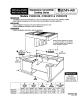
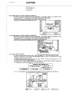
SINGLE See side clearance--------)l note below. '" L - ;- Min. Clearanoe 44"46cm ,, 4 3t4" 1 I 12.ol I Required ,._,, 17 1/2" ,,I, r-_ ]J-----1 _ [] II I cm * _ 1 I I t" Grease Container [__,,_ --_-- 12 1/2 -_ 31.76crn 4, K SEE NOTE BELOW LJSEENOT E BELOW DOUBLE See side clearance_I note below. _ _- 4, Min. Clearance ,,. Required 17 1/2" 44.46 cm 1" II ILli I _fl _12 1/2L-_ 31.
Installing Cabinetry Over Your Jenn-Air Grill A = 30" (76.2 cm) minimum clearance between the top of the cooking platform and the bottom of an unprotected wood or metal cabinet. A = 24" (60.96 cm) minimum when bottom of wood or metal cabinet is protected by not less than !/4" (0.635 cm). FLAME RETARDANT millboard covered with no less than no. 28 MSG sheet steel, 0.015" (0.038 cm) stainless steel, 0.024" (0.061 cm) aluminum or copper.
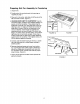
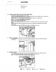
Preparing Unit For Assembly In Countertop 1, Unpack Unit. 2. Provide cutout for countertop and duct openings as required per page 1. 3. Place unit in the cutout, and slide unit all the way to the left hand side of cutout. (Figure 1). 4. HOLDING DOWN UNIT TO COUNTERTOP: Use the hold down straps, provided in the hardware package, to secure unit to the countertop. These straps may be positioned on the left, front, and back sides of the unit. (See figure 1A).
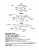
C_.stomer SeP:ic_ Z40 EawardsSLreet,SE C1eve!and, Tennessee 37311 Tei: _22-472-3333 Fax:_23-478-6710 I0. FLOOR VENT CUTOUT (JOISTS AS SHOWN) - Check the direction of the floor joists (see illustration), tf the joists' direction is as shown, locate the cutout on the '7" as illustrated. The cutout must miss the floarjoists! - Cutout may be moved from side to side on line to clear floor joist. - Recheck your dimensions and make the cutout. 11.
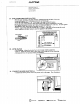
2J-gEawa_dsStreeL SE C;eveiand,Tennessee37311 Tel:423-477.-;333 Fax:'_23-J-78-67! 0 13. INSTALL BLOWER (PRIOR TO INSTALLING RANGE) - Refer to your vent plan. It may be desirable to attach part of the ducting to the blower before it is installed. - Position the blower (see illustration) and attach it to the floor with at least two (2) screws. - Apply duct tape around blower exhaust/duct joint. THROUGH THROUGH OUTSIDE WALl. THE FLOOR r It rfZfTflVfl_l/ .---. ff¢ j METAL ffJ'--J_ .." E.
2_0Eawar_sE,tr_e[ % C'.m:e,anaTe.nr_z_ee_7._11 Fax_2._-478-_70 16. CONNECT ELECTRICAL (FOUR CONDUCTOR WIRE) - CAUTION: Make sure power to cable is OFF. - Remove the range electrical service cover located on the back, lower left-hand corner. Remove the ground strapscrew and bend the strap up as shown. - [nstall a 3/4 (1.19 cm) cable clamp in the hole provided, below the terminal block. - Strip 3" (7.62 cm) of outer insulation from the cable. - Strip lt2" (1.27 era) of insulation from each wire.
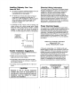
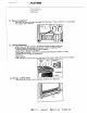
Cus[ome r _ePdc_ 2_0EdwardsStreet, SE Ceveian_.Tennessee373I I Te!: a22-'72-3333 t9. ANTI-TIP BRACKET INSTALLATION - With the unit installed in the final location, establish left side and back of the unit. - Locate left bracket 5/8" (1.58 cm) in from the left of the unit. - Locate the right bracket 27 718" (70.80 cm) to the right of the left bracket. - Locate the rear of both brackets flush to the back of the unit if a backsplash is not used.
240 EdwardsS_r_e[.SE C[eveiane,Tennessee3731; Tei:423.47Z-,_333 F,a×:422-47_,-3710 22. INSTALL FLEX DUCT - Attach the flex duet to the blower and range (See illustration), duet clamp at each connection. 3. Using a screwdriver, securely tighten CHECK OPERATION - Unpack and in,stall grill element in one side and cooking cartridge in other side. - Be sure to remove all packaging materials from unit prior to applying power. - Switch the electrical circuit breaker to the ON position.