
Installation guide


C_.stomer SeP:ic_
Z40EawardsSLreet,SE
C1eve!and,Tennessee37311
Tei: _22-472-3333
Fax:_23-478-6710
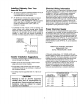
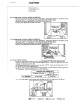
I0.
FLOOR VENT CUTOUT (JOISTS AS SHOWN)
- Check the direction of the floor joists (see illustration), tf the joists' direction is as shown, locate
the cutout on the '7" as illustrated. The cutout must miss the floarjoists!
- Cutout may be moved from side to side on line to clear floor joist.
- Recheck your dimensions and make the cutout.
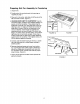
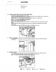
11. FLOOR VENT CUTOUT (JOISTS AS SHOWN)
- Check the direction of the floor joists (see illustration). If the joists' direction is as shown, locate
the cutout on the T as illustrated. The cutout must miss the floor joist!!
- Cutout may be moved from front to back on line to clear floor joist.
- Recheck your dimensions and make the cutout.
!
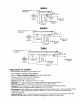
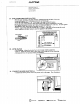
12. WALL VENT CUTOUT
- Locate the vertical studs in the rear wall. Studs are usually t6 _ (40.64 cm) center to center.
- Wil! the vent duct be 6" (15.24 cm) round throug.h the wall or 3 1t4" x 10" (8.26 cm x 25.4 era)
rectangle, vertically inside the wall?
- See Ducting Instructions for rear duct inside the wall. NOTE: Cutout in walt must clear 3 1/4" x
10" (8.26 cm x 25.4 era) transition elbow.
- Locate the closest stud to your proposed vent hole location. Use the following chart to figure the
_X" dimension. See the illustration for the other dimensions.
) "X" MINIMUM
i VERTICAL DUCT INSIDE WALL
6" Round (15.24 era) 3¼" x 10"
(8-26 cm x 25.4 era)
}. 4" (10.16 cm) 6" (15.24 era)
- A 1" (2.54 cm) length of duct must protrude through the wall for connection to the Blower.
{ _ |c:.os_sTt
8'h" 61t_-
t43._ crop q
._4,_,'/I,\G Admiral 7! -'ttvl'_jl::NN-.A;l::t "_iI!,1_i€ C,_.e_