
Installation guide


2J-gEawa_dsStreeL SE
C;eveiand,Tennessee37311
Tel:423-477.-;333
Fax:'_23-J-78-67!0
13.
14.
I5.
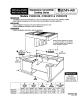
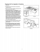
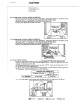
INSTALL BLOWER (PRIOR TO INSTALLING RANGE)
- Refer to your vent plan. It may be desirable to attach part of the ducting to the blower before it
is installed.
- Position the blower (see illustration) and attach it to the floor with at least two (2) screws.
- Apply duct tape around blower exhaust/duct joint.
THROUGH THROUGH
OUTSIDE WALl. THE FLOOR
r It .---.
rfZfTflVfl_l/ ff¢ ffJ'--J_ E.Z .."
j I
METAL DUCT
INSTALL ELECTRICAL oucr TAPE
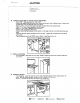
- NOTE: Observe all local electrical codes.
- CAUTION: Make sure power to cable is OFF:
- Locate the electric power supply in the floor or wall, any place in the shaded areas which will
clear the blower.
- Direct Connect. Pull through 5' (152.4 cm) of electrical cable.
- Use three or four conductor copper stranded power cable (see front cover for proper wire size). If
four conductor wire is used, see #16 for connection to range.
- See front cover for proper supply connection. . _1"[ _eTRIC,_t.k
I \I
4,/,"(_1._=_ SHADEDAREA \ i
---,4 ----- V
/ i _L_,._ _._ :-o_.tt. 1 $" (782 ¢m}
1 I
ELECTRICAL CAI_
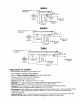
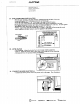
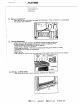
CONNECT ELECTRICAL (THREE CONDUCTOR WIRE)
- CAUTION: Make sure power to cable is OFF.
- Remove the range electrical service cover, located on the back, lower lefthand corner.
- [nstatl a 3/4" (I.91 cm) clamp in the hole provided below the terminal block.
- Strip 3" (7.62 cm) of outer insulation from the cable.
- Strip It2" (I .27 era) of insulation from each wire.
- Pull the cable through the cable clamp. Attach the BLACK, RED, and WHITE wires (see
illustration). Tighten the terminal block nuts and the cable clamp and install cover.