iNstaLl BOTTOM MOUNT BUILT-IN REFRIGERATOR RÉFRIGÉRATEUR ENCASTRÉ AVEC CONGÉLATEUR EN BAS For questions about features, operation/performance, parts, accessories, or service, call: 1-800-JENNAIR (1-800-536-6247) or visit our website at www.jennair.com. In Canada, call: 1-800-JENNAIR (1-800-536-6247), or visit our website at www.jennair.ca.
TABLE OF CONTENTS TABLE DES MATIÈRES INTRODUCTION INTRODUCTION Refrigerator Safety.......................................................................................3 Sécurité du réfrigérateur.........................................................................19 VARIANTS AND ACCESSORIES VARIANTES ET ACCESSOIRES 36" Single-Door Models ...........................................................................4 36" and 42" French Door Models ...................................................
INTRODUCTION REFRIGERATOR SAFETY Your safety and the safety of others are very important. We have provided many important safety messages in this manual and on your appliance. Always read and obey all safety messages. This is the safety alert symbol. This symbol alerts you to potential hazards that can kill or hurt you and others. All safety messages will follow the safety alert symbol and either the word “DANGER” or “WARNING.
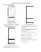
VARIANTS AND ACCESSORIES 36" SINGLE-DOOR MODELS Custom-Made Panel Design Features custom-made panels and custom hardware provided by the cabinetmaker for a seamless appearance designed to blend with existing kitchen cabinetry. Base Model Numbers: JB36NXFXLE, JB36NXFXRE ARMOIRE KIT NUMBER: W10663562 RISE™ Stainless Design Features stainless steel wrapped doors and new RISE™ handles.
36" AND 42" FRENCH DOOR MODELS Custom-Made Panel Design Features custom-made panels and custom hardware provided by the cabinetmaker for a seamless appearance designed to blend with existing kitchen cabinetry. Base Model Numbers: JF42NXFXDE, JF36NXFXDE ARMOIRE KIT NUMBER: W10663562, W10663564 RISE™ Stainless Design Features stainless steel wrapped doors and new RISE™ handles.
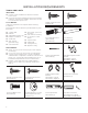
INSTALLATION REQUIREMENTS TOOLS AND PARTS IMPORTANT: Installer: Leave Installation Instructions with the homeowner. Homeowner: Keep Installation Instructions for future reference. Save these Installation Instructions for the local electrical inspector’s use. TOOLS NEEDED: Gather the required tools and parts before starting installation.
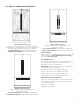
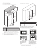
PRODUCT DIMENSIONS Width dimensions were measured from hinge to hinge. When leveling legs are fully extended to 1¹⁄₄" (3.2 cm) below rollers, add 1¹⁄₄" (3.2 cm) to the height dimensions.
FRENCH DOOR BOTTOM MOUNT MODELS DOOR SWING DIMENSIONS The location must permit both doors to open to a minimum of 90°. Allow 4¹⁄₂" (11.4 cm) minimum space between the side of the refrigerator and a corner wall. NOTE : More clearance may be required if you are using wood overlay panels, custom handles, or extended handles. 36" SINGLE DOOR MODEL 56⁵⁄₈" (143.8 cm) 831/8" (211.1 cm) 58³⁄₄" (149.2 cm) 90º 110º 36" (91.4 CM) AND 42" (106.
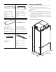
SITE PREPARATION CLOSED SOFFIT CABINET OPEN TO CEILING OR SOFFIT CABINET Ceiling or soffit 6" air gap min. 25" (max.) No obstruction above refrigerator 84" (213.3 cm) 25" (max.) Cabinet 84" (213.3 cm) Width (A) Cabinet Width (A) MODEL WIDTH A 36 36" (91.4 cm) 42 42" (106.7 cm) These type of installations require a minimum of 6" (15.24 cm) of open space above the refrigerator. This space must not be blocked in any way, including soffits.
SECONDARY ANTI-TIP BOARDS ANTI-TIP BOARDS For open to ceiling or soffit cabinet constructions the refrigerator must be braced with the help of primary and secondary anti-tip boards. WARNING PRIMARY ANTI-TIP BOARDS IMPORTANT: It is recommended that primary anti-tip boards be installed before the refrigerator is installed. Boards must be long enough to fully cover the width of the compressor cover. Place the boards so that the bottom surfaces of the boards are 84" (213 cm) from the floor.
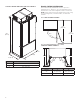
LOCATION REQUIREMENTS WARNING WATER SUPPLY REQUIREMENTS IMPORTANT : Do not use with water that is microbiologically unsafe or of unknown quality without adequate disinfection before or after the system. Systems certified for cyst reduction may be used on disinfected waters that may contain filterable cysts. Explosion Hazard Keep flammable materials and vapors, such as gasoline, away from refrigerator. Failure to do so can result in death, explosion, or fire.
WATER PRESSURE A cold water supply with water pressure between 30 psi and 120 psi (207 kPa and 827 kPa) is required to operate the water dispenser and ice maker. If you have questions about your water pressure, call a licensed, qualified plumber. A grounded 3 prong electrical outlet should be located within a specified number of inches from the right-hand side cabinets or end panel. See the chart following the illustration for the number of inches required for your model.
STAINLESS STEEL PANEL KIT INSTALLATION REQUIREMENTS CUSTOM WOOD PANEL DIMENSIONS AND INSTALLATION REQUIREMENTS Refer instructions received with full height door panel kit. Refer instructions received with Armoire kit. INSTALLATION INSTRUCTIONS UNPACK THE REFRIGERATOR 1. Place an appliance dolly under the left side of the refrigerator as shown. Place the corner posts from the packing materials over the trims as appropriate. Slowly tighten the strap. 2.
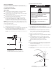
STYLE 1—SHUTOFF VALVE CONNECTION NOTE : If your water line connection does not look like Style 1, see “Style 2—Copper Line Connection.” 1. Unplug refrigerator or disconnect power supply. 1. 2. Unplug refrigerator or disconnect power. 3. Locate a 1/2" to 1¹⁄₄" (1.3 cm to 3.18 cm) vertical cold water pipe near the refrigerator. IMPORTANT : 2. There is not enough clearance to achieve a flush installation if a water shutoff valve is located in the wall behind the refrigerator.
CONNECT TO REFRIGERATOR OVERMOLD COUPLING (ON SOME MODELS) PARTS SUPPLIED 1/4" to 1/4" (6.35 mm to 6.35 mm) male-to-male coupling. A B C 21/2" (6.35 cm) max. A. Household water line B. Nut (purchased) C. Ferrule (purchased) 7" (17.78 cm) DISCRETE COUPLING (ON SOME MODELS) NOTE : The flexible, codes-approved water supply line should connect to the supply valve through the floor. 1. 2. Unplug the refrigerator or disconnect power. 3.
PLUG IN REFRIGERATOR 3. WARNING Using the original holes and the screws removed in Step 2, fasten the side trim to the refrigerator cabinet. NOTE : Make sure to fasten each trim piece to the side of the refrigerator cabinet from which it was removed. The tapered shaped edge should be forward with the notches aligning with the door hinges. TOP VIEW Electrical Shock Hazard Plug into a grounded 3 prong outlet. Do not remove ground prong. Do not use an adapter. A C B Do not use an extension cord.
After the refrigerator is leveled and aligned, remove the installation block from the door hinge and use it to check the spacing between the panels and adjacent cabinets. NOTE : The installation block is designed to provide accurate spacing for 3/4" (1.9 cm), 3/8" (9.53 mm) and 1/8" (3.18 mm). 3/4" (1.9 cm) LEVEL AND ALIGN REFRIGERATOR WARNING 1/8" (3.18 mm) Tip Over Hazard 3/8" (9.53 mm) 1. 2. Place top of cardboard carton or plywood under refrigerator. Remove dolly.
IMPORTANT : Adjust in small increments to keep from damaging the cabinet trim and causing problems with the door alignment or top grille fit. To avoid damage to the cabinet or leveling legs, do not apply more than 50 inch-pounds (5.65 Nm) of torque to the leveling bolts. The leveling legs can be extended to a maximum of 1¹⁄₄" (3.18 cm) below the rollers. 1.
INTRODUCTION SÉCURITÉ DU RÉFRIGÉRATEUR Votre sécurité et celle des autres est très importante. Nous donnons de nombreux messages de sécurité importants dans ce manuel et sur votre appareil ménager. Assurez-vous de toujours lire tous les messages de sécurité et de vous y conformer. Voici le symbole d’alerte de sécurité. Ce symbole d’alerte de sécurité vous signale les dangers potentiels de décès et de blessures graves à vous et à d’autres.
VARIANTES ET ACCESSOIRES MODÈLES AVEC PORTE SIMPLE DE 36 PO Conception de panneaux personnalisés Comporte des panneaux et du matériel personnalisés fournis par l’ébéniste pour une apparence harmonieuse conçue pour s’intégrer aux armoires de cuisine existantes. Numéros de modèles de base : JB36NXFXLE et JB36NXFXRE NUMÉRO D’ENSEMBLE POUR ARMOIRE : W10663562 Acier inoxydable RISE™ Portes avec habillage en acier inoxydable et nouvelles poignées RISE™.
MODÈLES AVEC PORTE À DOUBLE BATTANT DE 36 PO ET 42 PO Conception de panneaux personnalisés Comporte des panneaux et du matériel personnalisés fournis par l’ébéniste pour une apparence harmonieuse conçue pour s’intégrer aux armoires de cuisine existantes. Numéros de modèles de base : JF42NXFXDE et JF36NXFXDE NUMÉRO D’ENSEMBLE POUR ARMOIRE : W10663562 et W10663564 Acier inoxydable RISE™ Portes avec habillage en acier inoxydable et nouvelles poignées RISE™.
EXIGENCES D’INSTALLATION OUTILS ET PIÈCES IMPORTANT : Installateur : Remettre les instructions d’installation au propriétaire. Propriétaire : Conserver les instructions d’installation pour référence ultérieure. Conserver ces instructions d’installation pour consultation par l’inspecteur local des installations électriques.
DIMENSIONS DU PRODUIT Les dimensions de largeur ont été relevées d’une charnière à l’autre. Lorsque les pieds de nivellement sont totalement déployés de 1 ¹⁄₄ po (3,2 cm) au-dessous des roulettes, ajouter 1 ¹⁄₄ po (3,2 cm) à la hauteur totale.
MODÈLES DE RÉFRIGÉRATEUR AVEC CONGÉLATEUR EN BAS ET PORTE À DOUBLE BATTANT DIMENSIONS POUR L’OUVERTURE DES PORTES L’emplacement d’installation doit permettre l’ouverture des deux portes à un angle minimal de 90°. Laisser un espace libre d’au moins 4 ¹⁄₂ po (11,4 cm) entre le côté du réfrigérateur et un mur d’angle. REMARQUE : Un dégagement plus grand peut être nécessaire si l’on utilise des panneaux de bois décoratifs, des poignées personnalisées ou des poignées de plus grande profondeur.
PRÉPARATION DU SITE ARMOIRE À SOFFITE FERMÉ OUVERTURE VERS LE PLAFOND OU L’ARMOIRE SOFFITE Plafond ou soffite Espace de 6 po min. 25 po (max.) 84 po (213,3 cm) Aucune obstruction au-dessus du réfrigérateur 25 po (max.
PANNEAUX ANTIBASCULEMENTS SECONDAIRES PANNEAUX ANTIBASCULEMENTS Pour les constructions avec ouverture vers le plafond ou cabinet soffite, le réfrigérateur doit être arrimé à l’aide de panneaux antibasculements primaires et secondaires. AVERTISSEMENT PANNEAUX ANTIBASCULEMENTS PRIMAIRES IMPORTANT : On recommande la mise en place de panneaux antibasculements primaires avant l’installation du réfrigérateur.
EXIGENCES D’EMPLACEMENT AVERTISSEMENT SPÉCIFICATIONS DE L’ALIMENTATION EN EAU IMPORTANT : Ne pas utiliser pour le filtrage d'une eau microbiologiquement polluée ou de qualité inconnue en l'absence d'un dispositif de désinfection adéquat avant ou après le système. Les systèmes certifiés pour la réduction de kyste peuvent être utilisés pour l'eau désinfectée qui peut contenir des kystes filtrables.
PRESSION D’EAU Une alimentation en eau froide avec une pression entre 30 lb/po2 et 120 lb/po2 (207 kPa et 827 kPa) est nécessaire pour faire fonctionner le distributeur d’eau et la machine à glaçons. Pour toute question au sujet de la pression de l’eau, faire appel à un plombier qualifié agréé. Une prise électrique à trois broches avec mise à la terre doit être placée à une distance définie des armoires de droite ou du panneau situé à l’extrémité.
EXIGENCES D’INSTALLATION DE L’ENSEMBLE DE PANNEAUX EN ACIER INOXYDABLE EXIGENCES D’INSTALLATION ET DIMENSIONS DES PANNEAUX DE BOIS PERSONNALISÉS Consulter les instructions reçues avec l’ensemble de panneaux de porte pleine grandeur. Consulter les instructions reçues avec l’ensemble pour armoire.
RACCORDEMENT À LA CANALISATION D’EAU Lire toutes les instructions avant de commencer. 4. IMPORTANT : Si on doit mettre en marche le réfrigérateur avant que la canalisation d’eau ne soit connectée, placer la machine à glaçons à arrêt. Brancher sur une alimentation en eau potable uniquement. Ne pas utiliser pour le filtrage d'une eau microbiologiquement polluée ou de qualité inconnue en l'absence d'un dispositif de désinfection adéquat avant ou après le système.
7. 8. 9. 10. 11. Enfiler la bague et l’écrou de compression sur le tube en cuivre comme illustré. Insérer l’extrémité de la canalisation directement dans l’extrémité de sortie, aussi loin que possible. Visser l’écrou de compression sur l’extrémité de sortie du raccord à l’aide d’une clé à molette. Ne pas serrer excessivement la bride ou la bague. Ceci provoquera l’écrasement du tube de cuivre. Fermer le robinet d’arrêt de la canalisation d’eau. Lover le tube de cuivre.
BRANCHER LE RÉFRIGÉRATEUR 3. AVERTISSEMENT En utilisant les trous d’origine et les vis retirées à l’étape 2, fixer la garniture latérale à la caisse du réfrigérateur. REMARQUE : Veiller à fixer chaque garniture sur le côté de la caisse du réfrigérateur d’où elle a été retirée. Le bord de forme conique doit être en avant, les encoches alignées avec les charnières de la porte. VUE DE DESSUS Risque de choc électrique Brancher sur une prise à 3 alvéoles reliée à la terre.
Une fois le réfrigérateur à niveau et aligné, retirer la cale d’installation de la charnière de porte et l’utiliser pour vérifier l’espace entre les panneaux et les armoires adjacentes. REMARQUE : La cale d’installation est conçue pour assurer un espacement précis de 3/4 po (1,9 cm), 3/8 po (9,53 mm) et 1/8 po (3,18 mm). 3/4 po (1,9 cm) RÉGLAGE DE L’APLOMB ET ALIGNEMENT DU RÉFRIGÉRATEUR AVERTISSEMENT 1/8 po (3,18 mm) 3/8 po (9,53 mm) 1. 2.
IMPORTANT : Ajuster par petits à-coups pour éviter d’endommager la garniture de l’armoire et causer des problèmes d’alignement de la porte ou d’insertion de la grille supérieure. Pour éviter d’endommager l’armoire ou les pieds de réglage de l’aplomb, ne pas appliquer sur les boulons un couple supérieur à 50 lb-po (5,65 Nm). Les pieds de réglage de l’aplomb peuvent être déployés à un maximum de 1 ¹⁄₄ po (3,18 cm) au-dessous des roulettes. 1.
NOTES 35
NOTES 36
NOTES 37
NOTES 38
NOTES 39
W11511880B /™ ©2021 JennAir. All rights reserved. Used under license in Canada. Tous droits réservés. Utilisé sous licence au Canada.