
Installation guide
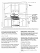
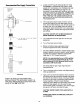

CONNECTING THE RANGE
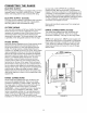
FIGURE 4
3-Wire Service Cord or Conduit Installation
1. Insure that the copper ground strap IS CONNECTED
between the middle post of the main terminal
connection block and the range chassis.
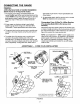
2. If bare copper or aluminum wiring is used, attach
adapter lugs as shown in figure 4. (See Bare Wire
Connection), Torque specifications are shown below.
3, The middle wire of the service cord or ground lead of
3-wire conduit MUST connect to the neutral (middle)
post of the main terminal block. The other two wires of
the service cord or conduit connect to the outside
posts of the main terminal connection block. Polarity is
unimportant. If using bare wire, attach wire to
appropriate lug as shown. Torque specifications are
shown below.
4. An appropriate strain relief for service cord or conduit
MUST be attached to the conduit plate.
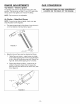
ACCEPTABLE - 3 WIRE PLUG INSTALLATION
WHITE
BLACK
RED
MAIN TERMINAL
CONNECTIONBLOCK
NtDDLE WIRE OF
SERVICE CORD
OR CONDUIT
GROUNDINGSTRAP
CONNECTEDAT
FACTORY
STRAIN
CONDUIT RELIEF
PLATE
FLOOR
' FORUSE WITH CONDUIT.
RECEPTACLE
MOUNTEDFLUSH
TO WALL
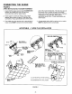
ADAPTER
LUGSLOCATED
IN LITERATUREKIT
RED
BLACK
WHITE
BARE WIRE TOROU_ SP[CIFICATION£
LUGATTACHEDTO TERHINALDLOCK- 20 IN.L6
10.14 20 IN-L6
O 25 IN-LB
4.5 3S Ii-Lfi
ALTERNATIVE" INSTALLATION
REMOVEBRACKET.FLIP
& RE-ATTACHWITH SHALL
HOLEVISIBLE,
OUTLET RECEPTACLE TO BE ROTATE
IN ACCORDANCE WITH LOCAL CODES
FIGURE 4
-6-