Service This manual is to be used by qualified appliance technicians only. Maytag does not assume any responsibility for property damage or personal injury for improper service procedures done by an unqualified person.
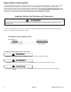
Important Information Pride and workmanship go into every product to provide our customers with quality products. It is possible, however, that during its lifetime a product may require service. Products should be serviced only by a qualified service technician who is familiar with the safety procedures required in the repair and who is equipped with the proper tools, parts, testing instruments and the appropriate service information.
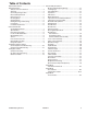
Table of Contents Important Information .................................................... 2 Safety Information Safety Practices for Servicer .................................... 4 Servicing .................................................................. 4 Connecting Range to Gas ........................................ 5 Electrical Requirements ........................................... 5 Extension Cord ........................................................ 5 Receiving Oven ........................
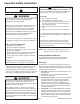
Important Safety Information Recognize this symbol as a safety precaution. ! ! ! Due to the nature of cooking, fires can occur as a result of overcooking or excessive grease. Although a fire is unlikely, if one occurs proceed as follows: WARNING If the information in this manual is not followed exactly, a fire or explosion may result causing property damage, personal injury or death. There can be a risk of injury or electrical shock while performing services or repairs.
Important Safety Information 5. Do not smoke—Never smoke while servicing gas ranges, especially when working on piping that contains or has contained gas. 6. Check range when service is completed—After servicing, make visual checks on electrical connection, and check for gas leaks. Inform consumer of the condition of range before leaving. 7. Adhere to all local regulations and codes when performing service.
Important Safety Information • Other areas of the oven can become hot enough to cause burns, such as vent openings, window, oven door and oven racks. • To avoid steam burns, do not use a wet sponge or cloth to wipe up spills on hot cooking area. • Do not store combustible or flammable materials, such as gasoline or other flammable vapors and liquids near or in oven. • Do not clean oven door gasket located on back of the door.
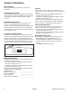
General Information This manual provides basic instructions and suggestions for handling, installing and servicing dual fuel ranges. The directions, information, and warnings in this manual are developed from experience with, and careful testing of the product. If the unit is installed according to this manual, it will operate properly and will require minimal servicing. A unit in proper operating order ensures the consumer all the benefits provided by clean, modern electric and gas cooking.
General Information Specifications Refer to individual Technical Sheet for specification information. Service Placement of the Oven This freestanding range must be placed in the kitchen or comparable room. All safety guidelines must be followed (see Chapter 2) and free air flow around the range is essential. Do Not Block Air Vents All air vents must be kept clear during cooking. If air vents are covered during operation, the oven may overheat.
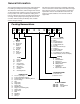
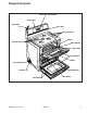
Range Description Electronic Oven Control Backguard Data Plate Oven Vent Surface Controls Broiler Surface Burners Bake Element Oven Rack Oven Window Broiler Anti-Tip Bracket Leveling Leg Bake Element Oven Racks Door Gasket ©2004 Maytag Services 16023417 9
Troubleshooting Procedures ! WARNING To avoid risk of electrical shock, personal injury or death; disconnect power and gas to oven before servicing, unless testing requires power and/or gas. ! CAUTION • • • • Verify proper grounding before checking for trouble. Be careful of the high voltage circuit. Discharge the high voltage capacitor.
Troubleshooting Procedures ! WARNING To avoid risk of electrical shock, personal injury or death; disconnect power and gas to oven before servicing, unless testing requires power and/or gas.
Troubleshooting Procedures ! WARNING To avoid risk of electrical shock, personal injury or death; disconnect power and gas to oven before servicing, unless testing requires power and/or gas. NOTES: 1 2 3 4 5 6 “Action Taken” applies as long as the condition exists. If the condition goes away, the control recovers. If there is a cook function or timer active, the function continues. The user cannot edit the function, and [Cancel] will cancel the cook mode. Flash rate: 0.2 seconds on, 0.1 second off.
Troubleshooting Procedures ! WARNING To avoid risk of electrical shock, personal injury or death; disconnect power and gas to oven before servicing, unless testing requires power and/or gas. Component Troubleshooting Problem Part or all of the appliance does not work Burners will not ignite; no spark at top burner. Burner will not ignite. No spark to burner ignitors when burner knob is rotated to “LITE” position. No spark or only random spark at one ignitor.
Troubleshooting Procedures ! WARNING To avoid risk of electrical shock, personal injury or death; disconnect power and gas to oven before servicing, unless testing requires power and/or gas. Problem Oven elements fail to operate or heat food. No oven operation in bake or broil. Broil element shuts off shortly after the start of selfclean operation. Bake and broil functions operate normally. No gas flows to burner. Ignitor glows red. Fan motor does not operate.
Troubleshooting Procedures ! WARNING To avoid risk of electrical shock, personal injury or death; disconnect power and gas to oven before servicing, unless testing requires power and/or gas. Problem Oven light does not operate. Self-clean cycle not working Oven door will not unlock Oven smokes/odor first few times of usage Failure Codes ©2004 Maytag Services Possible Cause Correction Failed oven lamp ......................................... • Check lamp and replace is necessary. Failed wiring....
Testing Procedures ! WARNING To avoid risk of electrical shock, personal injury or death; disconnect power and gas to oven before servicing, unless testing requires power and/or gas. Component Testing Illustration 5 K btu 9.2 K btu (2) 16 K btu 12 K btu Component Oven light socket Autolatch assembly with switch Disconnect wires and test for continuity per wiring diagram. 270° valve Refer to Parts Manual for correct autolatch switch associated with the correct manufacturing number.
Testing Procedures ! WARNING To avoid risk of electrical shock, personal injury or death; disconnect power and gas to oven before servicing, unless testing requires power and/or gas. Illustration Component Broil element, Lower Test Procedure Disconnect wire leads to element and measure resistance of terminals Measure voltage at broil element ..... Oven indicator light and Surface indicator light Measure voltage at indicator light. ... Rocker switch Measure continuity of switch positions: Closed ...
Testing Procedures ! WARNING To avoid risk of electrical shock, personal injury or death; disconnect power and gas to oven before servicing, unless testing requires power and/or gas. H2.5 Control Testing H2.5 Controlled Oven temperature adjustment (Upper Oven) H2.5 Controlled Oven temperature adjustment (Lower Oven) H2.5 Controlled H2.5 Controlled Temperature display Clock Display H2.5 Controlled 24 Hour Clock H2.5 Controlled Factory Default H2.5 Controlled Twelve hour off H2.
Testing Procedures ! WARNING To avoid risk of electrical shock, personal injury or death; disconnect power and gas to oven before servicing, unless testing requires power and/or gas. “Quick Test” Mode for Electronic Range Control Follow the procedure below to perform the Electronic Range Control (ERC) quick test. Instructions must be entered within 32 seconds of each other (via the touch pad) or the ERC will exit the quick test. 1. Press and hold the UPPER CANCEL and BROIL pads for 3 seconds. 2.
Testing Procedures ! WARNING To avoid risk of electrical shock, personal injury or death; disconnect power and gas to oven before servicing, unless testing requires power and/or gas. Component Electronic range control Engineering Test Mode Fault codes accessed through Engineering Test Mode Test Mode Test Procedure Results F1−1 –Upper Oven >650°F with door unlocked............................. Check actual upper oven temperature, if > 650°F check sensor. F1−2 –Lower Oven >650°F with door unlocked ....
Disassembly Procedures ! WARNING To avoid risk of electrical shock, personal injury, or death: disconnect electrical and gas supply before servicing. Moving and/or Replacing Range Maintop Removal 1. 2. 3. 4. 1. Disconnect power before servicing. 2. Remove surface burner control knobs by grasping knob and raising knob straight upward. 3. Remove screws securing infinite switch bracket to maintop. 4. Remove screws securing burner assemblies to maintop. 5. Remove screws securing maintop to chassis.
Disassembly Procedures ! To avoid risk of electrical shock, personal injury, or death: disconnect electrical and gas supply before servicing. WARNING Bake Element Oven Light Replacement 1. Disconnect power before servicing. 2. Remove oven door for easier accessibility, see "Oven Door(s)-Door Removal" procedure. 3. Remove screws securing bake element to back of oven cavity. 4. Gently pull element through cavity wall until terminals can be accessed. 5. Label and disconnect wiring and remove element. 6.
Disassembly Procedures ! WARNING To avoid risk of electrical shock, personal injury, or death: disconnect electrical and gas supply before servicing. Door Removal • Open door to stop position (approximately 4"), then grasp both sides of the door and lift up off hinges. • Lay door on a protected surface, liner side up. • Close door hinges completely to avoid personal injury. Door Replacement 1. Open door hinges to first stop position and align slots on the door with the hinge arms on the range. 2.
Disassembly Procedures ! To avoid risk of electrical shock, personal injury, or death: disconnect electrical and gas supply before servicing. WARNING Lower Oven Door Lower Latch Assembly NOTE: Removal of range from installation position is required. 1. Disconnect power before servicing. 2. Remove oven door, see "Oven Door(s)-Door Removal" procedure. 3. Remove range from installation position, see "Move and/or Replacing Range" procedure. 4. Remove maintop, see "Maintop Removal" procedure.
Disassembly Procedures ! WARNING To avoid risk of electrical shock, personal injury, or death: disconnect electrical and gas supply before servicing. Upper Oven Door Upper Latch Assembly 1. Disconnect power before servicing. 2. Remove oven door, see "Oven Door(s)-Door Removal" procedure. 3. Remove maintop, see "Maintop Removal" procedure. (Perform steps 1 – 6.) 4. Disconnect and label wiring from door lock switch and motor. 5. Remove screws securing latch assembly and slide assembly from range. 6.
Disassembly Procedures ! To avoid risk of electrical shock, personal injury, or death: disconnect electrical and gas supply before servicing. WARNING Oven Door Hinge NOTE: Removal of range from installation position is required. 1. Disconnect power before servicing. 2. Remove oven door, see "Oven Door(s)-Door Removal" procedure. 3. Remove maintop, see "Maintop Removal" procedure. (Perform steps 1 – 6.) 4. Remove appropriate side panel (left or right), see "Side Panel" procedure. 5.
Disassembly Procedures ! WARNING To avoid risk of electrical shock, personal injury, or death: disconnect electrical and gas supply before servicing. Hi-Limit Thermostat NOTE: Removal of range from installation position is required. 1. Disconnect power before servicing. 2. Remove range from installation position, see "Move and/or Replacing Range" procedure. 3. Remove screws securing main back shield and remove shield. 4. Remove screws securing thermostat to range main back. 5.
Disassembly Procedures ! WARNING To avoid risk of electrical shock, personal injury, or death: disconnect electrical and gas supply before servicing. Oven Cavity Components (Electric) Open or remove the oven door.
Appendix A ©2004 Maytag Services 16023417 A–1
Installation Instructions A–2 16023417 ©2004 Maytag Services
Installation Instructions ©2004 Maytag Services 16023417 A–3
Installation Instructions A–4 16023417 ©2004 Maytag Services
Installation Instructions ©2004 Maytag Services 16023417 A–5
Installation Instructions A–6 16023417 ©2004 Maytag Services
Installation Instructions ©2004 Maytag Services 16023417 A–7
Installation Instructions A–8 16023417 ©2004 Maytag Services
Installation Instructions ©2004 Maytag Services 16023417 A–9
Installation Instructions A–10 16023417 ©2004 Maytag Services
Installation Instructions ©2004 Maytag Services 16023417 A–11
Installation Instructions A–12 16023417 ©2004 Maytag Services
Installation Instructions ©2004 Maytag Services 16023417 A–13
Installation Instructions A–14 16023417 ©2004 Maytag Services
Installation Instructions ©2004 Maytag Services 16023417 A–15
Installation Instructions A–16 16023417 ©2004 Maytag Services
Installation Instructions ©2004 Maytag Services 16023417 A–17
Appendix B B–1 16023417 ©2004 Maytag Services
Use and Care ©2004 Maytag Services 16023417 B–2
Use and Care B–3 16023417 ©2004 Maytag Services
Use and Care ©2004 Maytag Services 16023417 B–4
Use and Care B–5 16023417 ©2004 Maytag Services
Use and Care ©2004 Maytag Services 16023417 B–6
Use and Care B–7 16023417 ©2004 Maytag Services
Use and Care ©2004 Maytag Services 16023417 B–8
Use and Care B–9 16023417 ©2004 Maytag Services
Use and Care ©2004 Maytag Services 16023417 B–10
Use and Care B–11 16023417 ©2004 Maytag Services
Use and Care ©2004 Maytag Services 16023417 B–12
Use and Care B–13 16023417 ©2004 Maytag Services
Use and Care ©2004 Maytag Services 16023417 B–14
Cleaning Procedures B–15 16023417 ©2004 Maytag Services
Cleaning Procedures ©2004 Maytag Services 16023417 B–16
Cleaning Procedures B–17 16023417 ©2004 Maytag Services
Cleaning Procedures ©2004 Maytag Services 16023417 B–18
Appendix C C–1 16023417 ©2004 Maytag Services
LP Conversion Instructions ©2004 Maytag Services 16023417 C–2
LP Conversion Instructions C–3 16023417 ©2004 Maytag Services
LP Conversion Instructions ©2004 Maytag Services 16023417 C–4
LP Conversion Instructions C–5 16023417 ©2004 Maytag Services