JENN-AIR® 36" AND 42" (91.4 CM AND 106.7 CM) ISLAND CANOPY RANGE HOOD HOTTE DE CUISINIÈRE JENN-AIR® POUR ÎLOT DE 36" ET 42" (91,4 CM ET 106,7 CM) Installation Instructions and Use & Care Guide For questions about features, operation/performance, parts, accessories, or service in the U.S.A., call: 1-800-JENNAIR (1-800-536-6247) or visit our website at www.jennair.com. In Canada, call: 1-800-807-6777, or visit our website at www.jennair.ca.
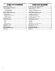
TABLE OF CONTENTS TABLE DES MATIÈRES RANGE HOOD SAFETY .................................................................3 INSTALLATION REQUIREMENTS ................................................5 Tools and Parts ............................................................................5 Location Requirements ................................................................5 Venting Requirements..................................................................6 Electrical Requirements ..................
RANGE HOOD SAFETY Your safety and the safety of others are very important. We have provided many important safety messages in this manual and on your appliance. Always read and obey all safety messages. This is the safety alert symbol. This symbol alerts you to potential hazards that can kill or hurt you and others. All safety messages will follow the safety alert symbol and either the word “DANGER” or “WARNING.
IMPORTANT SAFETY INSTRUCTIONS WARNING: TO REDUCE THE RISK OF FIRE, ELECTRIC SHOCK, OR INJURY TO PERSONS, OBSERVE THE FOLLOWING: ■ Use this unit only in the manner intended by the manufacturer. If you have questions, contact the manufacturer. ■ Before servicing or cleaning the unit, switch power off at service panel and lock the service disconnecting means to prevent power from being switched on accidentally.
INSTALLATION REQUIREMENTS Tools and Parts Gather the required tools and parts before starting installation. Read and follow the instructions provided with any tools listed here. Tools needed ■ Level ■ Drill with 1¼" (3.0 cm), ³⁄₈" (9.5 mm), ⁷⁄₆₄" (2.75 mm) and ¹⁄₈" (3.
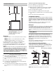
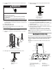
For the most efficient and quiet operation: Use a straight run or as few elbows as possible. Installation Dimensions ■ B C A D A. Ceiling height B. Hood height from ceiling to bottom of the range hood: A-C-D=B C. 24" (61.0 cm) minimum to 36" (91.4 cm) maximum suggested hood height. D. Countertop height IMPORTANT: Minimum distance “C”: 24" (61.0 cm) from electric cooking surface. Minimum distance “C”: 27" (68.6 cm) from gas cooking surface. Suggested maximum distance “C”: 36" (91.
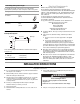
Calculating Vent System Length Electrical Requirements To calculate the length of the system you need, add the equivalent feet (meters) for each vent piece used in the system. Vent piece 8" (20.3 cm) round 45° elbow 2.5 ft (0.8 m) 90° elbow 5.0 ft (1.5 m) Maximum equivalent vent length is 35 ft (10.7 m). Example Vent System 90 elbow Observe all governing codes and ordinances.
Range Hood Mounting Screws Installation 1. Determine and mark the centerline on the ceiling where the range hood will be installed, considering the requirements for ceiling support structures. See the “Location Requirements” section. Make sure the range hood is centered over the cooking surface. 2. Tape template in place on the ceiling at the marked centerline. 3. Use a pencil to mark the mounting screws, wire access and duct hole locations on the ceiling.
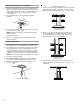
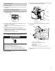
3. Remove the knockout in the terminal box cover and install a UL listed or CSA approved ¹⁄₂" strain relief. Connect Vent System 1. Install vent system. 2. Push duct over the exhaust outlet. Seal all connections with vent clamps. A B Non-Vented (recirculating) Installation 1. Attach the air deflector to the upper horizontal support using 4 mounting screws. A B A. Deflector B. Mounting screws 2. Measure the length of 8" (20.3 cm) duct needed to connect the transition to the deflector.
6. Use UL listed wire connectors and connect white wires (E) together. 3. Attach lower duct covers using a plastic bracket at each corner (4 needed). WARNING A B Electrical Shock Hazard C Electrically ground blower. A. Upper duct cover B. Lower duct cover C. Plastic bracket Connect ground wire to green and yellow ground wire in terminal box. Failure to do so can result in death or electrical shock. 7.
Heat Sensor Range Hood Controls A B C D E A. Power decrease B. Power increase C. Display D. Light E. Timer The control is equipped with a heat sensor that will turn on the blower to the highest speed if excessive heat occurs around the control area. ■ If the blower is On or Off, the blower will automatically set to the highest speed. “Auto” will appear in the display to indicate that the heat sensor has detected excessive heat.
RANGE HOOD CARE Cleaning IMPORTANT: Clean the hood and grease filters frequently according to the following instructions. Replace grease filters before operating hood. Exterior Surfaces: To replace charcoal filter: 1. Cover the grill that covers the blower motor with the charcoal filter so that the slots on the filter correspond to the pins on the sides of the motor protection grille. To avoid damage to the exterior surface, do not use steel wool or soap-filled scouring pads.
WIRING DIAGRAM Electronic User Interface CON2 GND N L W BK Y/G Electronic Power Board CON1 L NL NM LA S4 S3 S2 S1 P2 P4A P3 P4 P5 P9 P8 5 4 3 1 2 5 6 4 P7 3 P6 1 2 CON4 BU CON3 N P1 Y W BR W R BK Y BU GY CON8 Y BK BU BU CON7 Y/G Y BU CON 6 N L 1 CON 11 3 2 4 7 6 5 9 8 CON 5 Y/G BR YL W R BK CON 9 BU L GY Y N Y BU BU CON 12 Y M Y BU Y BU Y BU Y BU BU CON 10 13
ASSISTANCE OR SERVICE When calling for assistance or service, please know the purchase date and the complete model and serial number of your appliance. This information will help us to better respond to your request. If you need replacement parts If you need to order replacement parts, we recommend that you use only factory specified parts. Factory specified parts will fit right and work right because they are made with the same precision used to build every new appliance.
JENN-AIR® MAJOR APPLIANCE WARRANTY ONE YEAR LIMITED WARRANTY For one year from the date of purchase, when this major appliance is operated and maintained according to instructions attached to or furnished with the product, Jenn-Air brand of Whirlpool Corporation or Whirlpool Canada LP (hereafter “Jenn-Air”) will pay for factory specified parts and repair labor to correct defects in materials or workmanship. Service must be provided by a Jenn-Air designated service company.
SÉCURITÉ DE LA HOTTE DE CUISINIÈRE Votre sécurité et celle des autres est très importante. Nous donnons de nombreux messages de sécurité importants dans ce manuel et sur votre appareil ménager. Assurez-vous de toujours lire tous les messages de sécurité et de vous y conformer. Voici le symbole d’alerte de sécurité. Ce symbole d’alerte de sécurité vous signale les dangers potentiels de décès et de blessures graves à vous et à d’autres.
IMPORTANTES INSTRUCTIONS DE SÉCURITÉ AVERTISSEMENT : POUR RÉDUIRE LE RISQUE D'INCENDIE, CHOC ÉLECTRIQUE OU DOMMAGES CORPORELS, RESPECTER LES INSTRUCTIONS SUIVANTES : ■ Utiliser cet appareil uniquement dans les applications envisagées par le fabricant. Pour toute question, contacter le fabricant.
INSTALLATION REQUIREMENTS Outils et pièces Exigences d'emplacement Rassembler les outils et pièces nécessaires avant d’entreprendre l’installation. Lire et observer les instructions fournies avec chacun des outils de la liste ci-dessous. IMPORTANT : Observer les dispositions de tous les codes et règlements en vigueur. Confier l'installation de la hotte à un technicien qualifié.
■ Ne pas utiliser une bouche de décharge murale de 4" (10,2 cm) normalement utilisée pour un équipement de buanderie. ■ Utiliser un conduit métallique uniquement. Un conduit en métal rigide est recommandé. Ne pas utiliser de conduit de plastique ou d'aluminium. ■ Le système d'évacuation doit comporter un clapet. Si la bouche de décharge murale ou par le toit comporte un clapet, ne pas utiliser le clapet fourni avec la hotte de cuisinière.
Installation sans décharge à l'extérieur (recyclage) S’il n’est pas possible d'évacuer les fumées et vapeurs de cuisson à l’extérieur, on peut employer l'installation sans décharge à l'extérieur (recyclage) de la hotte, dotée d’un filtre à charbon actif et du déflecteur. La fumée et les vapeurs sont alors recyclés par la grille supérieure. Décharge à travers le toit Dans l’exemple suivant, la longueur théorique du circuit est inférieure au maximum de 35 pi (10,7 m).
INSTRUCTIONS D'INSTALLATION Préparation de l'emplacement ■ Il est recommandé que l'installation du circuit d'évacuation soit réalisée avant celle de la hotte. ■ Avant d’exécuter les découpages, vérifier qu'il existe un dégagement suffisant dans le plafond pour le conduit d’évacuation. ■ La hotte doit être installée à 24" (61 cm) min. des surfaces de cuisson électriques ou 27" (68,6 cm) min. des surfaces de cuisson au gaz, et à un maximum suggéré de 36" (91,2 cm) au-dessus de la surface de cuisson.
A Raccordement électrique A AVERTISSEMENT B Risque de choc électrique Déconnecter la source de courant électrique avant l'entretien. A. Supports verticaux B. Hauteur verticale 4. Fixer la hotte au support horizontal fixé au plafond à l'aide des 16 vis de 4 x 8 mm et serrer. A Replacer pièces et panneaux avant de faire la remise en marche. Le non-respect de ces instructions peut causer un décès ou un choc électrique. 1. Déconnecter la source de courant électrique. 2.
5. Connecter ensemble les conducteurs noirs (C) à l'aide de connecteurs de fils (homologation UL). 6. Connecter ensemble les conducteurs blancs (E) à l'aide de connecteurs de fils (homologation UL). 3. Fixer les sections inférieures du cache-conduit en plaçant une bride en plastique à chaque coin (4 sont nécessaires). A AVERTISSEMENT B C Risque de choc électrique A. Section supérieure du cache-conduit B. Section inférieure du cache-conduit C. Bride en plastique Relier le ventilateur à la terre.
■ Commandes de la hotte A B C D L'inclusion ou l'exclusion du filtre à charbon doit être sélectionnée pendant que l'éclairage et le moteur du ventilateur sont éteints. E Capteur de chaleur A. Diminution de la puissance B. Augmentation de la puissance C. Affichage D. Éclairage E. Minuterie Affichage Le module de commande est équipé d'un capteur de chaleur qui met le ventilateur en marche à la vitesse maximale si la température autour de la zone du module de commande est excessive.
■ Un signal sonore retentit lorsque le ventilateur atteint sa vitesse maximale. Power Decrease/Off (diminution de la puissance/ désactivé) ■ Ce bouton sert à éteindre le ventilateur ou à diminuer la vitesse du ventilateur. ENTRETIEN DE LA HOTTE Filtres d'installation sans décharge à l’extérieur (recyclage) : Le filtre à charbon n’est pas lavable. Celui-ci devrait durer pendant six mois dans des conditions d'utilisation normales. Remplacer par l'ensemble de filtre à charbon numéro W10272068.
SCHÉMA DE CÂBLAGE Interface-utilisateur électronique CON2 TERRE L N BL N JA/VE Carte électronique d'alimentation électrique CON1 L NL NM LA S4 S3 S2 S1 P2 P4A P3 P4 P5 P9 P8 5 4 3 1 2 5 6 4 P7 3 P6 1 2 CON4 BU CON3 N P1 JA BL MAR BL R N JA BU GRIS CON8 JA N BU BU CON7 JA/VE JA BU CON 6 N L 1 CON 11 3 2 4 7 6 5 9 8 CON 5 JA BU JA BU 26 JA M JA BU JA BU BU CON 10 JA/VE BR JA BL R CON 9 N L GRIS JA N BU JA BU BU CON 12
ASSISTANCE OU SERVICE Lors d’un appel pour assistance ou service, veuillez connaître la date d’achat, le numéro de modèle et le numéro de série au complet de l’appareil. Ces renseignements nous aideront à mieux répondre à votre demande. Si vous avez besoin de pièces de rechange Si vous avez besoin de commander des pièces de rechange, nous vous recommandons d’employer uniquement des pièces spécifiées par l’usine.
GARANTIE DES GROS APPAREILS MÉNAGERS JENN-AIR® GARANTIE LIMITÉE DE UN AN Pendant un an à compter de la date d'achat, lorsque ce gros appareil ménager est utilisé et entretenu conformément aux instructions jointes à ou fournies avec le produit, Jenn-Air, marque de Whirlpool Corporation ou Whirlpool Canada LP (ci-après désignées “Jenn-Air”) paiera pour les pièces spécifiées par l'usine et la main-d'œuvre pour corriger les vices de matériaux ou de fabrication.