
Instruction Sheet

8
Lighting the Electronic Igniters
The cooktop burners use electronic igniters in place of standing
pilots. When the cooktop control knob is pushed in and turned
to the IGNITE position, the system creates a spark to light the
burner. This sparking continues until a flame is present.
To Check Operation of the Cooktop Burners:
1. Push in and turn knobs to IGNITE. The cooktop burner
flame should light within 4 seconds. Turn the knobs to HI.
2. Turn the knobs to OFF.
3. Repeat steps 1 and 2 for the Lo and Simmer positions
4. If a burner does not light properly, turn the control knob to
OFF. Make sure the burner base and burner cap are in
their proper position.
5. Check that the power supply cord is plugged in and circuit
breaker has been tripped or household fuse has not blown.
6. Check that the shut-off valve is in the open position.
7. Check burner operation again.
If one or all of the burners do not light at this point, see the
“Warranty” section in the Use and Care Guide.
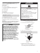
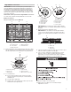
Low Flame Height Adjustment
Each burner flame has been factory set to the lowest position
available to provide reliable and constant reignition of the burner.
However, each burner can be adjusted.
For Propane gas conversion:
Tighten (clockwise) screw “C” snugly to set the minimum flame
height. Do not adjust for a higher flame.
For Natural gas conversion:
Tighten (clockwise) screw “C” to reduce flame height. Loosen
(counterclockwise) screw to increase flame height.
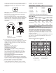
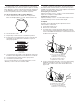
To Adjust:
The flame can be adjusted using the adjustment screws
underneath the control knob.
1. Set the burner flame to LO.
2. Remove the control knob.
3. For single valves, hold the knob stem with a pair of pliers.
Use a 3/32" (#0 [2.0 mm]) flat-blade screwdriver to turn the
screw located within the shaft of the control knob stem until
the flame is the proper size.
4. For the center burner dual valve, use a 3/32" (#0 [2.0 mm])
flat-blade screwdriver to turn the screw located on the
bottom, upper surface of the valve until the flame is the
proper size.
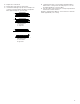
A. Correct
B. Incorrect
B
C
A
A. 3/32" (2.0 mm)—#0 flat-blade
screwdriver (shaft must be a
minimum of 2
1
/
2
" [6.4 cm] long)
B. Control knob stem opening
C. Adjustment screw location
B
A
A. Adjustment screw location
B. 3/32" (2.0 mm)—#0 flat-blade
screwdriver (shaft must be a
minimum of 2
1
/
2
" [6.4 cm] long)