
Installation Instruction


6
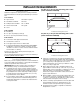
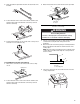
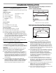
4. Make sure that the clips on each side of the cooktop line up
with the brackets in the cutout.
5. Push down on cooktop to snap the cooktop clips onto the
brackets installed in the cutout.
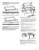
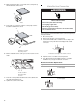
6. On the underside of the cooktop, loosen the 4 screws on the
slider.
7. Push the cooktop slider toward the side of the cabinet until
the slider and cabinet touch.
8. Tighten the screws on the slider.
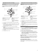
Make Electrical Connection
This cooktop is manufactured with a frame-connected, green (or
bare) ground wire.
1. Disconnect power.
2. Remove junction box cover if it is present.
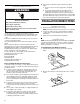
3. Connect the flexible cable conduit from the cooktop to the
junction box using a UL listed or CSA approved conduit
connector.
4. Tighten screws on conduit connector if present.
5. See “Electrical Connection Options Chart” to complete
installation for your type of electrical connection.
Electrical Connection Options Chart
A. Clip
A. Induction cooktop
B. Cooktop cutout
A. Side of cabinet
B. Cooktop slider
C. Screw
A
A
B
A
B
C
A. UL listed or CSA approved conduit connector
If your home has: Go to Section:
4-wire 4-Wire Cable from Home
Power Supply
3-wire 3-Wire Cable from Home
Power Supply
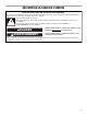
WARNING
Electrical Shock Hazard
Disconnect power before servicing.
Use 8 gauge copper wire.
Electrically ground cooktop.
Failure to follow these instructions can result in death,
fire, or electrical shock.
A
½"
(1.3 cm)
½"
(1.3 cm)