
Dimension Guide

JENNAIR DETAILED PLANNING DIMENSIONS
4 of 8
W11330665A
Installation Instructions: W11328306
IMPORTANT: Dimensional specications are provided for planning purposes only.
Do not make any cutouts based on this information. Refer to the Installation Guide before
selecting cabinetry, verifying electrical/gas connections, making cutouts or beginning installation.
All JennAir
®
appliances are appropriately UL, CUL or CSA approved.
®
/™ ©2019 JennAir. All rights reserved. Used under license in Canada.
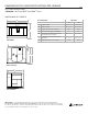
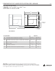
SMALL COFFEE SYSTEM - FLUSH INSTALLATION
JJB6424H – 23
7
⁄
16
" X 17
7
⁄
8
" X 18
15
⁄
16
"
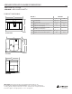
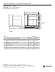
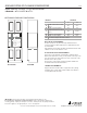
OPENING/CLEARANCE DIMENSIONS
FRONT VIEW SIDE VIEW
MODEL # JJB6424H
in cm
A
Width of ush inset cutout
(min.)
24
1
⁄
8
61.3
B Width of opening (min.) 22
1
⁄
16
56
C
Height of ush inset cutout
(min.)
18
5
⁄
16
46.46
D Height of opening (min.) 17
7
⁄
8
45.46
G Depth of cutout (min.) 22
1
⁄
2
57.1
e
Recommended junction box location
ELECTRICAL REQUIREMENTS
A 120 V, 60 Hz, AC only 15 A fused, grounded electrical
circuit is required. A time-delayed fuse or dedicated circuit is
recommended.
A grounded 3-prong outlet should be located in the back of the
cabinet. Do not use an extension cord.
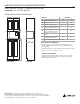
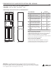
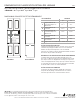
FLUSH INSTALLATION REQUIREMENTS
A 22½" (57.1 cm) minimum cutout depth is required. These
dimensions will result in a 1/8" (0.3 cm) reveal on the top, a 1/8"
(0.3 cm) reveal on the sides and a 7/16" (0.4 cm) reveal on the
bottom of the coffee system.
The front face of the cleats and spacers will be visible and
should be treated as a nished surface.
CABINET REQUIREMENTS
Support structure must be able to support 44.1 lbs. (20 kg)
including coffee system and contents. Make sure cabinet is
securely attached to the wall.
A
3/8" (1 cm)
Top Cleat*
13/16" (2 cm)
Side Cleat*
Height X Width
3/8" x 2-1/64" (1 cm X 5.1 cm)
Spacer (entire
depth
of cutout)
B
C
D
G
e