
Flush Kit Installation Instructions


3
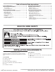
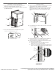
Parts Supplied
■ Deector bracket
■ Plastic spacers - (4) single ovens, (6) double ovens,
(4) combo oven
■ #8-18 x 1/4" (6.3 mm) screws - (2) for 27" (68.6 cm) models;
(4) for 30" (76.2 cm) models - deector bracket
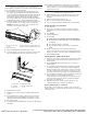
■ (4) #8-18 x 3/8" (9.5 mm) screws - oven feet
■ (2) feet
■ (2) front feet
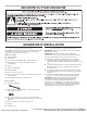
Location Requirements
IMPORTANT: Observe all governing codes and ordinances.
NOTE: Refer to the following “Location Requirements” and the
“Location Requirements” section of the Installation Instructions
provided with your built-in oven.
■ Cabinet opening dimensions that are shown must be used.
Given dimensions provide minimum clearance for the oven.
■ The recessed installation area must provide complete
enclosure around the recessed portion of the oven.
■ The oven support surface must be solid, level and ush with
the bottom of the cabinet cutout.
■ The oor must be able to support a total weight (microwave
and built-in oven) of 286 lbs (130 kg).
IMPORTANT: To avoid damage to your cabinets, check with
your builder or cabinet supplier to make sure that the materials
used will not discolor, delaminate or sustain other damage. This
oven has been designed in accordance with the requirements
of UL and CSA International and complies with the maximum
allowable wood cabinet temperatures of 194°F (90°C).
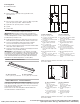
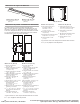
Deflector Bracket Dimensions
Cabinet Dimensions - Flush Installations
A 25" (63.5 cm) minimum cutout depth is required.
These dimensions will result in a 1/4" (6.3 mm) reveal on the top,
a 1/4" (6.3 mm) reveal on the sides, and a 1/8" (3.1 mm) reveal
on the bottom of the wall oven.
The front face of the cleats and platform will be visible and
should be treated as a nished surface.
*Cleats and spacers must be recessed 1
3
/
8
" (3.5 cm) from the
front of the cabinet.
*Cleats and spacers must be recessed 1
3
⁄
8
" (3.5 cm) from the
front of the cabinet.
A
27" (68.6 cm) Models
A. 26
15
⁄
16
" (68.4 cm) overall width
30" (76.2 cm) Models
A. 29
15
⁄
16
" (76.0 cm) overall width
27" (68.6 cm) Models
A. 5/8" (1.6 cm) top cleat*
B. 27
1
/
4
" (69.2 cm) minimum width
of flush inset cutout
C. 25
7
/
8
" (65.7 cm) minimum width
of opening
D. 44
5
/
16
" (112.5 cm) minimum
height of flush inset cutout
E. 43
11
/
16
" (110.9 cm)
recommended cutout height
F. 11/16" (1.7 cm) side cleat*
G. 1/2" x 2" (1.3 cm x 5.1 cm)
spacer the entire depth of the
cutout*
H. Recommended junction box
location
I. 4
5
/
8
" - 19
1
/
4
" (11.7 cm - 48.9 cm)
bottom of cutout to floor
J. 25" (63.5 cm) minimum depth of
cutout
30" (76.2 cm) Models
A. 5/8" (1.6 cm) top cleat*
B. 30
1
/
4
" (76.8 cm) minimum width
of flush inset cutout
C. 28
7
/
8
" (73.3 cm) minimum width
of opening
D. 44
5
/
16
" (112.5 cm) minimum
height of flush inset cutout
E. 43
11
/
16
" (110.9 cm)
recommended cutout height
F. 11/16" (1.7 cm) side cleat*
G. 1/2" x 2" (1.3 cm x 5.1 cm)
spacer the entire depth of the
cutout*
H. Recommended junction box
location
I. 4
5
/
8
" - 19
1
/
4
" (11.7 cm - 48.9 cm)
bottom of cutout to floor
J. 25" (63.5 cm) minimum depth of
cutout
A
B
C
D
E
F
F
I
H
H
J
G
G
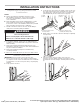
Front View Side View
Top View
B
AA
D
D
C
27" (68.6 cm) Models
A. 1/2" x 2"
(1.3 cm x 5.1 cm)
spacer the entire depth
of the cutout*
B. 25" (63.5 cm) depth of
cutout
C. 1
3
/
8
" (3.5 cm) recess
from front of cabinet
D. 11/16" (1.7 cm) side
cleat*
30" (76.2 cm) Models
A. 1/2" x 2"
(1.3 cm x 5.1 cm)
spacer the entire depth
of the cutout*
B. 25" (63.5 cm) depth of
cutout
C. 1
3
/
8
" (3.5 cm) recess
from front of cabinet
D. 11/16" (1.7 cm) side
cleat*
06-May-2019 13:38:42 EDT | RELEASED
In some European factories the letter "W" of the part code mentioned herein will be automatically
replaced by the number "4000" (e.g. "W12345678" becomes "400012345678")