JENN-AIR_ 30"AND 36" (76.2 CM AND 91.4 CM) RETRACTABLE (POP-UP)DOWNDRAFTVENTSYSIEM SYSI1_ME D'EXTRACTIONR_'IRACTABLE (CLAPE0.A. ASPIRATIONPARLEBASJENN-AII_ DE 30" ET36"(76,2 CM ET91,4 CM) iii InstallationInstructions and Use&Care Guide For questions about features, operation/performance, parts, accessories, or service in the U.S.A., call: 1-800-688-1100 or visit our website at www.jennair.com. In Canada, call: 1-800-807-6777, or visit our website at www.jennair.ca.
TABLEOF CONTENTS TABLEDESMATIERES VENT SYSTEM SAFETY ................................................................. 3 INSTALLATION REQUIREMENTS ................................................ 5 Tools and Parts ............................................................................ 5 Location Requirements ................................................................ 5 Electrical Requirements ............................................................... 7 Venting Requirements .................
VENTSYSTEMSAFETY Your safety and the safety of others are very important. We have provided many important safety messages in this manual and on your appliance. Always read and obey all safety messages. This is the safety alert symbol. This symbol alerts you to potential hazards that can kill or hurt you and others. All safety messages will follow the safety alert symbol and either the word "DANGER" or "WARNING.
iMPORTANT SAFETY iNSTRUCTiONS WARNING: TO REDUCE THE RISK OF FIRE, ELECTRIC SHOCK, OR INJURY TO PERSONS, OBSERVE THE FOLLOWING: m Use this unit only in the manner intended by the manufacturer. If you have questions, contact the manufacturer. m Before servicing or cleaning the unit, switch power off at service panel and lock the service disconnecting means to prevent power from being switched on accidentally.
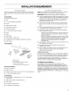
INSTALLATIONREQUIREMENTS Gather the required tools and parts before starting installation. Read and follow the instructions provided with any tools listed here. NOTE: Downdraft vent is installed directly behind the cooktop. Install the downdraft vent first, then install the cooktop. Tools Needed • • Jigsaw or keyhole saw • Drill • 1/8"(3 mm) drill bit for pilot holes • Pencil • Tape measure or ruler • Flat-blade screwdriver • Phillips screwdriver • 3/8"(9.
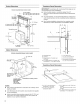
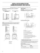
Product Dimensions Countertop Interior=mounted blower motor _30V4" Cutout Dimensions IMPORTANT: Countertops with a bull-nosed front edge are not recommended for these installations. model Top trim widths: (76.8 cm) for 30" (76.2 cm) vent 36V4 (92.1 cm) for 36 (91.4 cm) vent 13W' (34.3 cm) retractable vent height 11/2" (3.8 cm) 27" (68.6 cm) for 39" (76.2 cm) vent 33" (83.8 cm) for 36" (91.4 • Some models require a countertop deeper than 25" (63.
IMPORTANT: Observe all governing codes and ordinances. Save Installation Instructions for electrical inspector's use. • The downdraft vent must be connected only. It is the customer's responsibility to contact a qualified electrical installer, and to ensure that the electrical installation is adequate and in conformance with National Electrical Code, ANSI/NFPA 70 (latest edition), or CSA Standards C22.1-94, Canadian Electrical Code, Part 1 and C22.2 No.
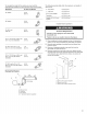
INSTALLATIONINSTRUCTIONS INTERIOR-MOUNTEDVENTMOTOR Island Location Vent system installed under a concrete slab using PVC sewer pipe. Front (Standard) Mounted Blower Motor Determine which venting method is best for your application. Vent system can terminate through either the wall or floor. Island location Front (standard) mounted blower motor Rear mounted blower motor B J q i! i!:___oo_,_............ ............................................................. A J K _o :,_ .........
To calculate the length of the system you need, add the equivalent feet (meters) for each vent piece used in the system. Vent Piece 6" (15.2 cm) Round 45 ° elbow 2.5 ft The following example falls within the maximum vent length of 35 ft (8.9 m). (0.8 m) 90 ° elbow 2 - 90 ° elbow = 10.0 ft (3 m) 1 - wall cap = 0.0 ft (0.0 m) 8 ft (2.4 m) straight = 8.0 ft (2.4 m) Transition = 4.5 ft (1.4 cm) Length of 6" (15.2 cm) system = 22.5 ft (6.8 m) 5.0 ft (1.5 m) 6" (15.2 cm) wall cap 0.0 ft (0.
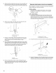
5= Attach the left and right side end caps to the downdraft vent. Place the end cap upon the overcounter support, slide the tab into the slot and snap into place over the the plastic tabs. A Determine which direction is best for your installation. When installed in a cabinet, vent system can exhaust through the bottom, right, left or rear of the cabinet. Bottom venting: Downdraft vent is shipped with blower in down venting position so no modification is required. See "Complete Installation" section.
4. Place the bottom tab of the blower box into the bottom mounting channel, 2. Lift up the blower box from the bottom mounting channel and set aside. @ @ B A A. Blower box B. Bottom mounting channel A. Blower box B. Bottom mounting channel 3= 5= Disconnect the wire connector from the blower motor. Tilt blower box top tab so it is flush with the vent box panel and position it under the top mounting bracket. Slide bracket into the "Z" slots and tighten the 2 hex/slotted head screws to secure. \ \
6. Install blower motor and mounting bracket assembly to the bracket just below the downdraft tower motor. The blower exhaust opening should fit through the hole in the large cover plate on the opposite side of the vent chamber where the small cover plate was removed. Replace the 2 blower motor mounting bracket screws and tighten. 9. Replace the vent box over the blower motor. B //' A. Blower motor B. Ventbox 10. Place the bottom tab of the blower box into the bottom mounting channel. C A.
_s_ _I_,_ _"_,_" _u,s_,,, Bowe_ _I_@oo NOTE: Optional blower motor mounting position (opposite side). The blower motor box assembly can also be moved to the opposite side (rear) of the vent box. 2. Lift up the blower box from the bottom mounting channel. @ B A A. Blower box B. Bottom mounting 3. Disconnect channel the wire connector from the blower motor. o A A. Panel B.
5. Lift up the panel from the bottom mounting channel. 8, Tilt blower box top tab so it is flush with the vent box panel and position it under the top mounting bracket. Slide bracket into the "Z" slots and tighten the 2 hex/slotted head screws to secure. @ B A A. Blower mounting B. Panel 6, channel Install the blower motor box assembly to the opposite side (rear) of the vent box with the vent located in the bottom venting position.
"_ 1= _ _ E •.... _ _ _ E_ ,,_,_ / =W _, Attach backdraft damper over 6" vent extension. Secure with vent clamp. Electrical Shock Hazard Disconnect power before servicing. Replace all parts and panels before operating. Failure to do so can result in death or electrical shock. A. 6" vent extension B. Backdraft damper 2. 1. Disconnect 2. Feed the power supply cable through the conduit connector and into the terminal box. power. Remove screw attaching the terminal box cover.
4, Connect the 2 white wires together using UL listed wire connectors. F 1, J C Push and hold the button on the top of the downdraft vent for a few seconds. The retractable section of the downdraft vent will rise, and the blower will start. Position the top trim over the retractable section and snap trim into place. Trim kits for matching your cooktop color are available from your dealer. E For information section. on ordering, see the "Assistance or Service" B A.
VENTSYSTEMUSE The retractable downdraft vent system is designed to remove smoke, cooking vapors and odors from the cooktop area. 2. • For best results, the vent should be operating before cooking is started. When cooking is complete: • If you use large or tall utensils, place them on the large rear element or burner surface. • A higher heat setting than normally used may be needed when the downdraft vent is operating. • This fan is suitable for use with solid-state speed controls. To Use: 1.
WIRING DIAGRAM PUSH BUTTON q UPIDOWN J _ SPEED [REGULATIONJ 5x20 800 mA Time Delay _RED _ RED 0 HH O d ( FILTER _ × "L__ iii__1:_I I t I, _ O _= BLKI)--Iax "-' BLK _}1 kSWITCHESJ GRY GRY FLAT CABLE I TRANSFORMER TOROIDAL 1 CN8 ORG GRY WHT d BLK z _RL1 CN2 z d z BLU BRW O BLK II LiNE iN 120 Vac 60 Nz 18
ASSISTANCEOR SERVICE When calling for assistance or service, please know the purchase date and the complete model and serial number of your appliance. This information will help us to better respond to your request. If you need replacement parts If you need to order replacement parts, we recommend that you use only factory specified parts. Factory specified parts will fit right and work right because they are made with the same precision used to build every new appliance.
JENN-AIR MAJOR APPLIANCEWARRANTY ONE YEAR LIMITED WARRANTY For one year from the date of purchase, when this major appliance is operated and maintained according to instructions attached to or furnished with the product, Jenn-Air brand of Whirlpool Corporation or Whirlpool Canada LP (hereafter "Jenn-Air") will pay for factory specified parts and repair labor to correct defects in materials or workmanship. Service must be provided by a Jenn-Air designated service company.
SECURITEDU SYSTEMEDEVENTILATION Votre securite et celle des autres est tres importante. Nous donnons de nombreux messages de s_curit_ importants dans ce manuel et sur votre appareil m_nager. Assurez-vous toujours lire tousles messages de s_curit_ et de vous y conformer. de Ce symbole d'alerte de s_curit_ vous signale les dangers potentiels de d_c_s et de blessures graves & vous et & d'autres.
iMPORTANTES iNSTRUCTiONS DE SECURITE AVERTISSEMENT : POUR REDUIRE LE RISQUE D'INCENDIE, CHOC ¢:LECTRIQUE OU DOMMAGES CORPORELS, RESPECTER LES INSTRUCTIONS SUIVANTES : I Utiliser cet appareil uniquement dans les applications envisag6es par le fabricant. Pour toute question, contacter le fabricant.
EXlGENCESD'INSTALLATION Rassembler les outils et pieces necessaires avant de commencer I'installation. Lire et observer les instructions fournies avec les outils de cette liste. REMARQUE : Le systeme d'extraction par le bas est installe directement derriere la table de cuisson. Installer d'abord le systeme d'extraction par le bas, puis la table de cuisson. IMPORTANT : Observer les dispositions reglements en vigueur.
Dimensions du produit Modele avec Plan de travail - Dimensions ventilateur rnont_ _ I'int_rieur Garniture sup_rieure : 301/4" (76,8 cm) pour syst_me d'extraction de 30" (76,2 cm) 361/4'' (92,1 cm) pour syst&me d'extraction de 36" (91,4 cm) 11/2"(3,8 cm) Couvercle de & d_couper IMPORTANT : Les plans de travail avec bords arrondis ne sont pas recommandes pour ces installations.
IMPORTANT : Observer les dispositions de tousles codes et reglements en vigueur. Conserver les instructions d'installation pour consultation par I'inspecteur des installations electriques. C'est au client qu'incombe la responsabilite de contacter un electricien qualifie et de veiller & ce que I'installation electrique soit adequate et realisee en conformite avec les prescriptions de la plus recente edition de la norme National Electrical Code, ANSI/NFPA 70, ou de la norme CSA C22.
INSTRUCTIONSD'I S.'I'ALLAT.ION VENTILATEUR MONTE A L'INTERIEUR Determiner quelle methode d'extraction est la plus appropriee. La sortie a I'exterieur du systeme d'extraction peut se faire travers le plancher ou & travers un mur. Configuration de cuisine en lot Syst_me d'extraction install_ sous une dalle de b_ton (utilisation de conduit de PVC pour _gout).
Pour calculer la Iongueur effective du systeme d'extraction necessaire, additionner les Iongueurs equivalentes (pieds/m_tres) de tousles composants utilises dans le systeme. Composant Syst_me de diam_tre 6" (15,2 cm) coude a 45 ° Risque du poids excessif (0,8 m) Utiliser deux ou plus de personnes installer le syst_me d'extraction. 2,5 pi coude a 90 ° pour d_placer et Le non=respect de cette instruction peut causer une blessure au dos ou d'autre blessure.
6. Fixer les pieds de support sur les c6tes de I'appareil - 2 vis pour chaque pied. Ne pas serrer les vis. A A / B A. Bofte du moteur de ventilateur B. Pied de support 7= 8= Faire intervenir 2 personnes ou plus, inserer le systeme d'extraction par le bas dans I'ouverture decoup6e dans I'ouverture du plan de travail. Veiller & placer I'appareil parallelement au c6te de I'ouverture decoup6e eta placer les brides de montage en chevauchement sur le plan de travail. A. Bride, avec rainures en "Z" B.
5. Incliner la patte superieure de la boite du ventilateur pour la placer en affleurement avec le panneau de la boite du systeme d'extraction et la positionner sous la bride de montage superieure. Faire glisser la bride dans les rainures en "Z" et serrer les 2 vis (t_te hex/fente droite). 3. Debrancher ventilateur. le connecteur du c&blage du moteur du B A. Mo teur du ventila teur B. Connecteur 4. Voir la section "Achever I'installation I'interieur".
7. Brancher le connecteur ventilateur, du c&blage sur le moteur du 10. Placer la patte inferieure de la boite du ventilateur dans le profile de montage inferieur. @ A A. Bofte B. Profil_ A. Moteur du ventilateur B. Connecteur 8. du c#blage Placer le raccord de tuyau d'evacuation de diam_tre 6" sur I'orifice de decharge; fixer avec les 4 vis. du systeme de montage d'extraction inf_rieur 11.
REMARQUE • Position de montage du ventilateur facultative (c6te oppose). On peut egalement deplacer la boite du moteur du ventilateur du c6te oppose (arriere) du circuit d'evacuation. 2. D@gager la boite du ventilateur inferieur en la soulevant. du profile de montage A A. Bofte du ventilateur B. Profil6 de montage inf6rieur 3. ' Deconnecter ventilateur. le connecteur du c&blage du moteur du B J A A. Panneau B. Moteur du ventilateur 1, montage \ arriere \ A. Mo teur du ventila teur B.
5, Degager le panneau du profile de montage inferieur en le soulevant. 8, Faire basculer I'onglet superieur de la boite du ventilateur de fa£;on & ce qu'il soit en affleurement avec le panneau de la boite du systeme d'extraction et le placer sous la bride de montage superieure. Faire glisser la bride dans les rainures en "Z" et serrer les 2 vis (t_te hex/fente droite). @ B ® A. Profi_ de montage du ven#lateur B.
• 1. l_ _ • %_ ._ • Connecter le clapet anti-reflux au raccord d'extension Le fixer avec la bride de fixation. de 6". Risque de choc _lectrique D_connecter rentretien. la source de courant 61ectrique avant Replacer pi_ces et panneaux avant de faire la remise en marche. A. Raccord de tuyau d'_vacuation B. Clapet anti-reflux 2. Le non=respect de ces instructions un d_c_s ou un choc 61ectrique. - diam. 6" Oter la vis fixant le couvercle du boitier de connexion. peut causer 1. Deconnecter 2.
4, Connecter ensemble les deux connecteurs connecteur de fils (homologation UL). blancs avec un Pour des renseignements "Assistance ou service". sur la commande, F voir la section B / / C / / Y @ E "D A. Garniture sup_rieure B. Bouton Marche/Arr_t C. Bouton de commande D. Embout E. Filtres A. Conducteur de liaison _ la terre B. Vis de fiaison C. Conducteurs _ la terre blancs D. Connecteurs E. Conducteurs de ills (homologation noirs F. Connecteur G.
UTILISATIONDU SYSTEMED'EXTRACTION 2. La fonction du systeme d'extraction par le bas est d'aspirer et evacuer hors de la cuisine les vapeurs et fumees de cuisson, sources d'odeurs. Lorsque la cuisson est termin_e : • Pour optimiser la performance, on devrait faire fonctionner systeme d'extraction avant d'entreprendre une cuisson. • Lors de I'emploi d'un ustensile de grande taille, placer celui-ci sur un brQleur ou element chauffant de grande taille, & I'arriere.
SCHI_MA DECh,BLAGE BOUTON POUSSOIR] HAUT/BAS j REGULATEUR_ DE VITESSE / Fusible temporis_, 5x20 800 mA MOTEUR X NOIR 0 HH O 0= d z z o_ _3 d z 37
ASSISTANCEOU SERVICE Lors d'un appel pour assistance ou service, veuillez connaitre la date d'achat, le numero de modele et le numero de serie au complet de I'appareil. Ces renseignements nous aideront & mieux repondre a votre demande. Si vous avez besoin de pi_ces de rechange Si vous avez besoin de commander des pieces de rechange, nous vous recommandons d'employer uniquement des pieces specifiees par I'usine.
GARANTIEDESGROS APPAREILSMENAGERSJENN-AIR GARANTIE LIMITI_E DE UN AN Pendant un an & compter de la date d'achat, Iorsque ce gros appareil menager est utilise et entretenu conformement aux instructions jointes a ou fournies avec le produit, Jenn-Air, marque de Whirlpool Corporation ou Whirlpool Canada LP (ci-apres designees "Jenn-Air") paiera pour les pieces specifiees par I'usine et la main-d'ceuvre pour corriger les vices de materiaux ou de fabrication.
W10201609C © 2009 All rights reserved. Tous droits reserves. ® Registered Trademark/TM Trademark of Jenn-Air U.S.A. Used under license by Maytag Limited in Canada. ® Marque deposeeF M Marque de commerce de Jenn-Air U.S.A. Emploi sous licence au Canada.