
Manual


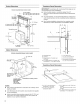

To calculate the length of the system you need, add the
equivalent feet (meters) for each vent piece used in the system.
Vent Piece 6" (15.2 cm) Round
45° elbow 2.5 ft
(0.8 m)
90° elbow 5.0 ft
(1.5 m)
6" (15.2 cm) 0.0 ft
wall cap (0.0 m)
31/4"x 10" (8.3 cm x 25.4 cm) 4.5 ft
to 6" (15.2 cm) transition (1.4 m)
6" (15.2 cm) to 31/4'' x 10" 1 ft
(8.3 cm x 25.4 cm) transition (0.3 m)
31/4"x 10" (8.3 cm x 25.4 cm) 5.0 ft
to 6" (15.2 cm) 90 ° elbow (1.5 m)
transition
6" (15.2 cm) to 31/4'' x 10" 5.0 ft
(8.3 cm x 25.4 cm) 90° elbow (1.5 m)
transition
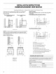
Example Vent System
C
2 ft (0.6 rn)
The following example falls within the maximum vent length of
35 ft (8.9 m).
2 - 90° elbow
1 - wall cap
8 ft (2.4 m) straight
Transition
Length of 6" (15.2 cm)
system
= 10.0 ft (3 m)
= 0.0 ft (0.0 m)
= 8.0 ft (2.4 m)
= 4.5 ft (1.4 cm)
= 22.5 ft (6.8 m)
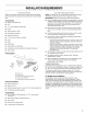
Excessive Weight Hazard
Use two or more people to move and install
downdraft vent.
Failure to do so can result in back or other injury.
1.
2.
3.
4.
Place cardboard or similar material on top of a flat surface
where you can easily assemble the downdraft vent system.
Remove parts packages, downdraft vent and blower box
from the carton.
Remove all shipping materials, tape and film from the
downdraft vent and blower box.
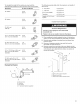
Remove screws from each side of the vent. Attach the left
and right side overcounter support brackets to the downdraft
vent and push up to align the screw holes. Use screws to
secure the brackets.
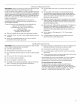
A. Overcounter support bracket
B. Blower motor box
C. Overcounter support bracket screw
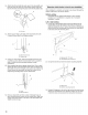
D
A. Blower motor
B. Transition
C. 90 ° elbows
D. 6" backdraft damper (suppfied)