JENN-AIR® 30" AND 36" (76.2 CM AND 91.4 CM) WALL-MOUNT CANOPY RANGE HOOD HOTTE DE CUISINIÈRE JENN-AIR® POUR MONTAGE MURAL 30" ET 36" (76,2 CM ET 91,4 CM) Installation Instructions and Use & Care Guide For questions about features, operation/performance, parts, accessories, or service in the U.S.A., call: 1-800-JennAir (1-800-536-6247) or visit our website at www.jennair.com. In Canada, call: 1-800-807-6777, or visit our website at www.jennair.ca.
TABLE OF CONTENTS TABLE DES MATIÈRES RANGE HOOD SAFETY .................................................................3 INSTALLATION REQUIREMENTS ................................................5 Tools and Parts ............................................................................5 Location Requirements ................................................................5 Venting Requirements..................................................................6 Electrical Requirements ..................
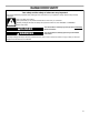
RANGE HOOD SAFETY Your safety and the safety of others are very important. We have provided many important safety messages in this manual and on your appliance. Always read and obey all safety messages. This is the safety alert symbol. This symbol alerts you to potential hazards that can kill or hurt you and others. All safety messages will follow the safety alert symbol and either the word “DANGER” or “WARNING.
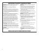
IMPORTANT SAFETY INSTRUCTIONS WARNING: TO REDUCE THE RISK OF FIRE, ELECTRIC SHOCK, OR INJURY TO PERSONS, OBSERVE THE FOLLOWING: ■ Use this unit only in the manner intended by the manufacturer. If you have questions, contact the manufacturer. ■ Before servicing or cleaning the unit, switch power off at service panel and lock the service disconnecting means to prevent power from being switched on accidentally.
INSTALLATION REQUIREMENTS Tools and Parts Gather the required tools and parts before starting installation. Read and follow the instructions provided with any tools listed here. Tools needed ■ Level ■ Drill with 1¼" (3.0 cm), ³⁄₈" (9.5 mm), ⁷⁄₆₄" (2.75 mm) and ¹⁄₈" (3.
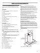
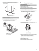
■ The vent system must have a damper. If the roof or wall cap has a damper, do not use the damper supplied with the range hood. ■ Use caulking to seal exterior wall or roof opening around the cap. ■ The size of the vent should be uniform. Installation Dimensions 13 ⁷⁄₈" (35 cm) 11 ⁷⁄₈" (30 cm) *8" (20.3 cm) min. 2" (5.1 cm) min.
■ Calculating Vent System Length 1. Connect a section of solid copper wire to the pigtail leads. 2. Connect the aluminum wiring to the added section of copper wire using special connectors and/or tools designed and UL listed for joining copper to aluminum. Follow the electrical connector manufacturer's recommended procedure. Aluminum/copper connection must conform with local codes and industry accepted wiring practices.
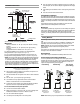
B F 2. Install vent cover bracket to wall about ¹⁄₈" (3.0 mm) away from the ceiling. Use 2 - 5 x 45 mm screws with 8 x 40 mm drywall anchors supplied. A B E C A. Vent cover bracket B. Centerline on wall Complete Preparation D A. Centerline B. Lower support bracket C. 5 x 45 mm screws D. Mounting height reference E. Fastener locations F. Wall 8. Place the support bracket on the template aligning it with the traced rectangle.
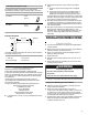
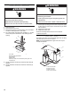
3. Remove the metal grease filter and secure the blower housing with two screws in the bottom holes located in the rear of the blower. Connect Vent System Vented Installation Only 1. Fit vent system over transition piece. 2. Seal connection with clamps. 3. Check that backdraft dampers work properly. For Non-vented (Recirculating) Installation: 1. Assemble the 3 parts of the deflector with 2 - 3.5 x 9.5 mm screws provided.
WARNING Make Electrical Connection WARNING Electrical Shock Hazard Electrically ground blower. Electrical Shock Hazard Disconnect power before servicing. Replace all parts and panels before operating. Failure to do so can result in death or electrical shock. 1. Disconnect power. 2. Remove terminal box cover. 3. Remove the knockout in the terminal box cover and install a UL listed or CSA approved ¹⁄₂" strain relief. 4.
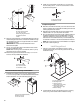
Install Filters 1. For non-vented (recirculating installations) install charcoal filter, wrapping it around the grease filter. 2. Place the charcoal filter mat around the grease filter and fix it in place by using the cap lock springs provided. 3. Position the upper cap and fix it in place using the cap lock spring provided. RANGE HOOD USE The range hood is designed to remove smoke, cooking vapors and odors from the cooktop area.
Audible Signal Activation and Deactivation The audible signals can be activated or deactivated by pressing the “LIGHT” button for 5 seconds. ■ If the audible signal is activated, a tone will sound, and “Snd” will appear on the display for 3 seconds. If the audible signal is deactivated, “Snd” will appear on the display for 3 seconds.
To Remove Metal Grease Filters To Replace Charcoal Filters 1. Turn off fan and lights. Check that halogen lamp is cool. 2. Remove the filter holder frame and grease filter using a flatblade screwdriver to turn the grease filter release screws 90° counterclockwise. 1. Turn fan and lights off. Check that halogen lamp is cool. 2. Remove the metal grease filters. See “Metal Grease Filters” section. 3. Remove the upper and side lock springs. 4. Clean or discard the charcoal filter. 5.
WIRING DIAGRAM WIRING BOX Electronic User Interface N L Y-G W Y-G BK CON2 Electronic Power Board N L NL NM LA S3 S2 S1 P1 P2 P4A P3 P4 P5 P8 BU R 4 3 P6 1 2 CON4 W 5 6 P7 R 1 2 GY 3 BK 4 BR BR 5 CON3 PRI SEC TRANSFORMER CON1 Y Y R BR R SEC Y TRANSFORMER BR Y PRI BU BK GY R W ADDITIONAL LAMPS ONLY PRESENT ON THE VERSIONS WITH 4 LAMPS Y-G Y Y ATTENTION!: 1 Y Y R Y 14 Y M BK BU BR Y Y Y Y-G GY R Y-G W BR
ASSISTANCE OR SERVICE When calling for assistance or service, please know the purchase date and the complete model and serial number of your appliance. This information will help us to better respond to your request. If you need replacement parts If you need to order replacement parts, we recommend that you use only factory specified parts. Factory specified parts will fit right and work right because they are made with the same precision used to build every new appliance.
JENN-AIR® MAJOR APPLIANCE WARRANTY ONE YEAR LIMITED WARRANTY For one year from the date of purchase, when this major appliance is operated and maintained according to instructions attached to or furnished with the product, Jenn-Air brand of Whirlpool Corporation or Whirlpool Canada LP (hereafter “Jenn-Air”) will pay for factory specified parts and repair labor to correct defects in materials or workmanship. Service must be provided by a Jenn-Air designated service company.
Notes 17
SÉCURITÉ DE LA HOTTE DE CUISINIÈRE Votre sécurité et celle des autres est très importante. Nous donnons de nombreux messages de sécurité importants dans ce manuel et sur votre appareil ménager. Assurez-vous de toujours lire tous les messages de sécurité et de vous y conformer. Voici le symbole d’alerte de sécurité. Ce symbole d’alerte de sécurité vous signale les dangers potentiels de décès et de blessures graves à vous et à d’autres.
IMPORTANTES INSTRUCTIONS DE SÉCURITÉ AVERTISSEMENT : POUR RÉDUIRE LE RISQUE D'INCENDIE, CHOC ÉLECTRIQUE OU DOMMAGES CORPORELS, RESPECTER LES INSTRUCTIONS SUIVANTES : ■ Utiliser cet appareil uniquement dans les applications envisagées par le fabricant. Pour toute question, contacter le fabricant.
EXIGENCES D'INSTALLATION Outillage et pièces Rassembler tous les outils et pièces nécessaires avant d'entreprendre l'installation. Lire et observer les instructions fournies avec chaque outil de la liste suivante.
*REMARQUE : La cheminée de la hotte est réglable; on peut l'ajuster en fonction de la hauteur disponible sous plafond ou soffite, et selon la distance “X” entre le bas de la hotte et la surface de cuisson. Pour des hauteurs sous plafond plus élevées, un ensemble d'extension de cheminée en acier inoxydable (pièce n° W10272071) est disponible chez votre marchand ou chez un distributeur de pièces autorisé. L'extension de cheminée remplace la section supérieure de cheminée fournie avec la hotte.
REMARQUE : On déconseille l'emploi de conduit flexible. Un conduit flexible peut causer une rétropression et des turbulences de l'air, ce qui réduit considérablement la performance. La sortie à l'extérieur du circuit d'évacuation peut se faire à travers le toit ou à travers un mur. Pour la sortie à travers un mur, on doit employer un raccord coudé (90°). Exemple de circuit d'évacuation système de décharge.
INSTRUCTIONS D’INSTALLATION Préparation de l'emplacement Il est recommandé d'installer le circuit d'évacuation avant de procéder à l'installation de la hotte. ■ Avant d'exécuter les découpages, vérifier la disponibilité d'un espace de passage suffisant dans le plafond ou le mur pour le circuit d'évacuation. ■ Avant de sélectionner la hotte à installer, mesurer la hauteur libre sous plafond et la hauteur maximum disponible sous la hotte. 1. Déconnecter la source de courant électrique. 2.
Dernières étapes de la préparation 3. Retirer le filtre à graisse métallique et fixer le carter du ventilateur avec deux vis placées dans les trous inférieurs, situés à l’arrière du ventilateur. 1. Déterminer et marquer toutes les lignes de découpage nécessaires sur le mur pour le passage du circuit d'évacuation. Installer le circuit d'évacuation avant la hotte. Voir la section “Circuit d'évacuation - Critères à respecter”. 2.
Installations sans décharge à l'extérieur (recyclage) 1. Utiliser les 2 vis fournies de 3,5 x 9,5 mm pour assembler les 3 parties du déflecteur. La largeur du déflecteur assemblé doit correspondre à la largeur de la bride de cache-conduit déjà installée. Raccordement électrique AVERTISSEMENT C A Risque de choc électrique B Déconnecter la source de courant électrique avant l'entretien. Replacer pièces et panneaux avant de faire la remise en marche. A. Largeur de la bride de cache-conduit B.
6. Connecter ensemble les conducteurs blancs (F) - utiliser un connecteur de fils (homologation UL). AVERTISSEMENT Installation des filtres 1. Pour les installations sans décharge à l’extérieur (recyclage), installer un filtre à charbon facultatif, en l’enveloppant autour du filtre à graisse. 2. Placer le revêtement souple du filtre à charbon autour du filtre à graisse et le fixer à l'aide des ressorts du système de verrouillage du couvercle fournis. 3.
■ Lorsque le ventilateur fonctionne en raison d'un niveau de chaleur excessif détecté par le capteur de chaleur, on ne peut pas réduire la vitesse du ventilateur. ■ Lorsque le niveau de température de la hotte retombe à un niveau normal, le ventilateur retourne au réglage qui avait été effectué avant que le niveau de chaleur excessif ne soit détecté.
ENTRETIEN DE LA HOTTE DE CUISINIÈRE Nettoyage IMPORTANT : Nettoyer fréquemment la hotte et les filtres à graisse - appliquer les instructions suivantes. Réinstaller les filtres à graisse avant de faire fonctionner la hotte. Avant d'entreprendre le nettoyage de la hotte, attendre le refroidissement des lampes. Surfaces externes Nettoyer la hotte avec un détergent doux et un chiffon doux.
SCHÉMA DE CÂBLAGE BOÎTIER DE CONNEXION Interface-utilisateur électronique N L JA-VE BL JA-VE N CON2 Carte électronique d'alimentation électrique N L NL NM LA S3 S2 S1 P1 P2 P4A P3 P4 P5 P8 BU R 4 3 P6 1 2 CON4 BL 5 6 P7 R 1 2 GRIS 3 N 4 MAR MAR 5 CON3 PRI SEC TRANSFORMATEUR CON1 JA JA R MAR R BU N GRIS JA -VE 1 JA JA JA N BU JA M MAR JA GRIS BL JA -VE JA-VE R R MAR JA JA PRI MAR TRANSFORMATEUR JA JA SEC R LAMPES ADDITIONNELLES DISPONI
ASSISTANCE OU SERVICE Lors d’un appel pour assistance ou service, veuillez connaître la date d’achat, le numéro de modèle et le numéro de série au complet de l’appareil. Ces renseignements nous aideront à mieux répondre à votre demande. Si vous avez besoin de pièces de rechange Si vous avez besoin de commander des pièces de rechange, nous vous recommandons d’employer uniquement des pièces spécifiées par l’usine.
GARANTIE DES GROS APPAREILS MÉNAGERS JENN-AIR® GARANTIE LIMITÉE DE UN AN Pendant un an à compter de la date d'achat, lorsque ce gros appareil ménager est utilisé et entretenu conformément aux instructions jointes à ou fournies avec le produit, Jenn-Air, marque de Whirlpool Corporation ou Whirlpool Canada LP (ci-après désignées “Jenn-Air”) paiera pour les pièces spécifiées par l'usine et la main-d'œuvre pour corriger les vices de matériaux ou de fabrication.
W10274303G © 2009. All rights reserved. Tous droits réservés. ® Registered Trademark/TM Trademark of Jenn-Air, U.S.A. Used under license by Maytag Limited in Canada. ®Marque déposée/TM Marque de commerce de Jenn-Air, U.S.A. Emploi sous licence par Maytag Limited au Canada.