
installation instructions

5
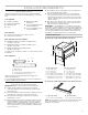
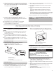
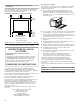
■ Microwave oven must be connected to the proper electrical
voltage and frequency as specied on the model/serial/rating
plate. The model/serial/rating plate is located underneath the
control panel along the oven vent.
■ The microwave oven rated 120/240 V, 20 A, has
4 wires (L1, L2, N, and G) in the ex conduit, and should
be connected to a 20 A maximum-rated circuit, overcurrent
protected on both the L1 and L2 circuits.
■ A time-delay fuse or circuit breaker is recommended.
■ Flexible cable from the microwave oven should be
connected directly to the junction box.
■ Do not cut the conduit. The length of conduit provided is for
serviceability of the microwave oven.
■ A UL listed or CSA approved conduit connector must be
provided.
■ If the house has aluminum wiring, follow the procedure
below:
Connect the aluminum wiring using special connectors
and/or tools designed and UL listed for joining copper to
aluminum.
Follow the electrical connector manufacturer’s recommended
procedure. Aluminum/copper connection must conform with
local codes and industry accepted wiring practices.
For power requirements, refer to the following table:
Voltage Microwave With Convection Oven
120/240 VAC 15 A
120/208 VAC 15 A
INSTALLATION INSTRUCTIONS
Spacer Kit Installation
NOTES:
■ The microwave oven spacer kit allows the microwave oven
to be installed in an 17
7
/
16
" to 17
7
/
8
" (44.1 cm to 45.3 cm)
maximum cutout height.
■ If your cabinet cutout height is more than 17
7
/
16
" (44.1 cm),
you must install the spacer kit. Proceed to “Assemble Spacer
Kit.”
■ If your cabinet cutout height is less than 17
7
/
16
" (44.1 cm),
you do not have to install the spacer kit. Proceed to “Prepare
Built-In Microwave Oven.”
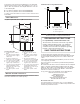
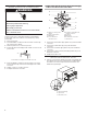
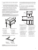
Assemble Spacer Kit
1. Attach the bottom vent to spacer bars using four
3/8" (9.5 mm)
hex-head washer screws.
NOTE: Spacer bar anges should be facing out.
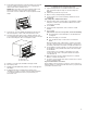
Install Spacer Kit
1. Center assembled microwave oven spacer kit against lower
front edge of the cabinet cutout.
2. Using an 1/8" (3.2 mm) drill bit, drill through the mounting
holes in the spacer bars to create pilot holes.
3. Attach the assembled spacer kit to the cabinet using four
3/4" (1.9 cm)
( at-head screws. Do not overtighten screws.
Prepare Built-In Microwave Oven
1. Locate existing wiring to avoid drilling into or severing wiring
during installation.
2. To avoid oor damage, set the microwave oven onto
cardboard prior to installation. Do not use handle or any
portion of the front frame for lifting.
3. Remove the shipping materials and tape from the microwave
oven.
4. Remove and set aside racks and other items from inside the
microwave oven.
5. Remove the hardware package from inside the bag
containing literature.
6. Move the microwave oven and cardboard close to the
microwave oven’s nal location.
A
A. Model/serial/rating plate
A
B
C
D
D
A. Bottom vent
B. Spacer bar flange
C. Spacer bars
D. 3/8" (9.5 mm) hex-head washer screws
A
B
A. 3/4" (1.9 cm) flat-head screws
B. Spacer kit assembly
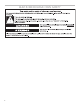
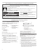
WARNING
Excessive Weight Hazard
Use two or more people to move and install
microwave oven.
Failure to do so can result in back or other injury.