
Flush Installation Instructions

3
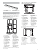
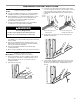
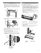
Front View
Deector Bracket Dimensions
27" (68.6 cm) Models
A.
³⁄4
" (19 mm) top cleat*
B. 27
¼
" (69.2 cm) minimum
width of ush inset cutout
C. 25
7
⁄8
" (65.7 cm) minimum
width of opening
D. 30
7
⁄16
" (77.3 cm) minimum
height of ush inset cutout
E. 29
11
⁄16
" (75.4 cm)
recommended cutout height
F.
11
⁄16
" (17 mm) side cleat*
G.
½
" x 2" (13 mm x 5.1cm)
spacer the entire depth
of the cutout*
H. Recommended junction
box location
I. 4
5
⁄8
" - 32" (11.7 - 81.3 cm)
bottom of cutout to oor
J. 25" (63.5 cm) minimum
depth of cutout
30" (76.2 cm) Models
A.
³⁄4
" (19 mm) top cleat*
B. 30
¼
" (76.8 cm) minimum
width of ush inset cutout
C. 28
7
⁄8
" (73.3 cm) minimum
width of opening
D. 30
7
⁄16
" (77.3 cm) minimum
height of ush inset cutout
E. 29
11
⁄16
" (75.4 cm)
recommended cutout height
F.
11
⁄16
" (17 mm) side cleat*
G.
½
" x 2" (13 mm x 5.1cm)
spacer the entire depth
of the cutout*
H. Recommended junction
box location
I. 4
5
⁄8
" - 32" (11.7 - 81.3 cm)
bottom of cutout to oor
J. 25" (63.5 cm) minimum
depth of cutout
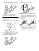
Single Ovens Undercounter - Flush Installations
(without cooktop installed above)
Side View
*Cleats and spacers must be recessed 1
3
⁄8" (3.5 cm) from the
front of the cabinet.
27" (68.6 cm) Models
A. 26
15
⁄16
" (68.4 cm) overall width
30" (76.2 cm) Models
A. 29
15
⁄16
" (76.0 cm) overall width
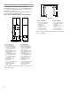
Cabinet Dimensions - Single Ovens, Flush Installations
A 25" (63.5 cm) minimum cutout depth is required.
These dimensions will result in a ¼" (6 mm) reveal on the top,
a ¼" (6 mm) reveal on the sides, and a
1
⁄8" (3 mm) reveal on
the bottom of the wall oven.
The front face of the cleats and platform will be visible and
should be treated as a nished surface.
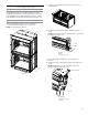
Single Ovens Installed in Cabinet - Flush Installation
27" (68.6 cm) Models
A. Recommended junction box
location
B.
³⁄4
" (19 mm) top cleat*
C. 27
¼
" (69.2 cm) minimum
width of ush inset cutout
D. 25
7
⁄8
" (65.7 cm) minimum
width of opening
E. 30
7
⁄16
" (77.3 cm) minimum
height of ush inset cutout
F. 29
11
⁄16
" (75.4 cm)
recommended cutout height
G.
11
⁄16
" (17 mm) side cleat*
H.
1
⁄2
" x 2" (13 mm x 5.1 cm)
spacer the entire depth
of the cabinet*
I. 4
1
⁄16
" (10.3 cm) bottom
of cutout to oor
30" (76.2 cm) Models
A. Recommended junction box
location
B.
³⁄4
" (19 mm) top cleat*
C. 30
¼
" (76.8 cm) minimum
width of ush inset cutout
D. 28
7
⁄8
" (73.3 cm) minimum
width of opening
E. 30
7
⁄16
" (77.3 cm) minimum
height of ush inset cutout
F. 29
11
⁄16
" (75.4 cm)
recommended cutout height
G.
11
⁄16
" (17 mm) side cleat*
H.
1
⁄2
" x 2" (13 mm x 5.1 cm)
spacer the entire depth
of the cabinet*
I. 4
1
⁄16
" (10.3 cm) bottom
of cutout to oor
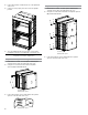
Front View
*Cleats and spacers must be recessed 1
3
⁄8" (3.5 cm) from the
front of the cabinet.
Top View
27" (68.6 cm) Models
A.
1
⁄2
" x 2" (13 mm x 5.1 cm)
spacer the entire depth
of the cutout*
B. 25" (63.5 cm) depth
of cutout
C. 1
3
⁄8
" (3.5 cm) recess
from front of cabinet
D.
11
⁄16
" (17 mm) side cleat*
30" (76.2 cm) Models
A.
1
⁄2
" x 2" (13 mm x 5.1 cm)
spacer the entire depth
of the cutout*
B. 25" (63.5 cm) depth
of cutout
C. 1
3
⁄8
" (3.5 cm) recess
from front of cabinet
D.
11
⁄16
" (17 mm) side cleat*
*Cleats and spacers must be recessed 1
3
⁄8" (3.5 cm) from the
front of the cabinet.
A
A
B
C
D
E
F
F
I
H
H
J
G
G
A
A
B
C
D
E
F
G
G
I
H
H
AA
B
D
D
C