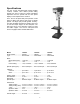
Operating Instructions and Parts Manual 15-Inch Vari-Speed Drill Press Models: J-A3816, J-A5816, J- A5818 Model J-A3816 WMH TOOL GROUP, Inc. 427 New Sanford Road LaVergne, Tennessee 30786 Ph.: 800-274-6848 www.wmhtoolgroup.com Model J-A5816 Part No.
Warranty and Service Lathe Accessories Machine Accessories Mobile Bases Safety Equipment Specialty Items Vise Accessories Air ToolsContractor Air Tools-Industrial Air Tools-Light Industrial Lubrication Palet Trucks Rigging Equip.
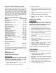
Table of Contents Warranty and Service ................................................................................................................................................ 2 Table of Contents ...................................................................................................................................................... 3 Warnings...................................................................................................................................................
Warnings 1. Read and understand the entire owner's manual before attempting assembly or operation. 2. Read and understand warnings posted on the machine and in this manual. Failure to comply with all of these warnings may cause serious injury. 3. Replace warning labels if they become obscured or removed. 4. This band saw is designed and intended for use by properly trained and experienced personnel only.
24. Check for damaged parts. Before further use of the tool, a guard or other part that is damaged should be carefully checked to determine that it will operate properly and perform its intended function - check for alignment of moving parts, binding of moving parts, breakage of parts, mounting, and any other conditions that may affect its operation. 25. A guard or other part that is damaged should be properly repaired or replaced. 26.
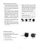
Safety Instructions for Drill Presses 6. Always wear protective eye wear when operating, servicing or adjusting machinery. Eyewear shall be impact resistant, protective safety glasses with side shields complying with ANSI Z87.1 specifications. Use of the eye wear which does not comply with ANSI Z87.1 specifications could result in severe injury from breakage of eye protection. See Figure B. 1. All work shall be secured using either clamps or a vise to the drill press table.
Specifications The JET 15-Inch Vari-Speed Drill Presses, Models J-A3816, J-A5816, and J-A5818 provide drilling speeds from 400 to 5,000 rpm. Simple handwheel adjustment sets the speeds with an LED speed display on the faceplate of the machine. JET's 15-inch vari-speed drill press provides a solid base for drilling and offers a wide range of spindle speeds. The large quill provides greater accuracy. The large worktable provides the operator with room to work and ample support for the workpiece.
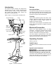
Introduction Set-up This manual includes operating and maintenance instructions for the JET 15-Inch Vari-Speed Drill Presses, Models J-A3816, J-A5816, and J-A5818. This manual also includes parts listings and illustrations of replaceable parts. Securing the Base Refer to Figure 1 for key features of the drill press. The base of the drill press has four mounting holes. The drill press should be level and rest solidly on the floor.
1. The head assembly must be locked to the column so the thrust produced by drilling will not force the head assembly up the column. LED Speed Display 2. The work table must be locked to the column so it will not be forced down the column. 3. Be sure the belt is tightened to the proper tension. 4. DO NOT start to drill the workpiece until making certain the workpiece is held down securely. 5. BEFORE turning the speed control handwheel in either direction. Depth Stop Speed control Handwheel 6.
Indication of Extreme Speeds and Feeds 3. Remove head cover. A drill that splits up the web is evidence of too much feed or insufficient tip clearance at the center as a result of improper grinding. The rapid wearing away of the extreme outer corners of the cutting edges indicates that the speed is too high. A drill chipping or braking out at the cutting edges indicates that either the feed is too heavy or the drill has been ground with too much tip clearance. 4. Remove belt.
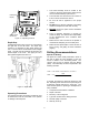
Adjustments Table Adjustment The table can be raised or lowered to accommodate the height of the component being drilled (refer to Figure 4). To raise or lower the table, loosen the lock handle. Then use the hand crank to move the table to the desired height. Then retighten the lock handle. Figure 4 – Table Adjustment Head Adjustment Change the radial position of the drill head only if the drill press base is secured to the floor.
230 Volt Operation Electrical Referring to Figure 7: 115 Volt Operation If 230V, single-phase operation is desired, the following instructions must be followed: Referring to Figure 6: 1. Disconnect the machine from the power source. As received from the factory, your drill press is ready to run at 115-volt operation. This drill press, when wired for 115 volt, is intended for use on a circuit that has an outlet and a plug that looks like the one illustrated in (A).
Grounding Instructions The drill press with a 230-volt plug should only be connected to an outlet having the same configuration (D, Fig. 7). No adapter is available or should be used with the 230-volt plug. This tool must be grounded while in use to protect the operator from electric shock. Important: In all cases (115 or 230 volts), make certain the receptacle in question is properly grounded. If you are not sure, have a registered electrician check the receptacle.
Troubleshooting Problem Spindle does not turn. Spindle noisy. Drill stalls. Probable Cause Suggested Remedy Circuit breaker tripped. Reset circuit breaker. Branch circuit breaker tripped or fuse blown. Reset Open wire in switch circuit. Repair open circuit. Defective switch. Repair switch. Broken drive belt. Replace drive belt. Damaged spindle bearings. Replace bearings. Worn spline. Replace spline. Worn drive belt. Check condition of belt.
Parts List - Head Models J-A5816 and J-A5818 Item Part No. Description Size Qty. 1 ...............5507580 ...................Chuck (with Key).................................................. .................................... 1 2A .............5507495 ...................Arbor .................................................................... #2 MT x JT3................ 1 3A .............5507496A.................Spindle ................................................................. .............
Parts List - Head Models J-A5816 and J-A5818 Item Part No. Description Size Qty. 55 .............5041140 ...................Vaiable Speed Pulley (Spindle) ........................... .................................... 1 55A ...........5513510 ...................Hex Nut ............................................................... .................................... 1 55B ...........5513511 ...................SHCS .................................................................. ..................
Exploded View — Head Models J-A5816 and J-A5818 17
Parts List - Head Model J-A3816 Item Part No. Description Size Qty. 1 ...............5507580 ...................Chuck (with Key).................................................. .................................... 1 2A .............5507495 ...................Arbor .................................................................... #2 MT x JT3 ............... 1 3A .............5507496A.................Spindle Assembly ............................................... ...................................
Parts List - Head Model J-A3816 Item Part No. Description Size Qty. 64 .............9138011 ...................Self Tapping Screw.............................................. #10 x 3/4 Type A......... 4 69 .............J-5518168 ................Pulley Cover (w/door & latch) .............................. .................................... 1 70 .............J-5518169 ................Face Plate ............................................................ .................................... 1 75 .....
Exploded View — Head Model J-A3816 69 76 70 63 16 64 61 51 62 55 54 52 55B 55A 35 34 27 57 89 53 50 44 94 33 28 100 42 26A 25A 24A 19A 18A 45 46 49 98 49 29 96 21 44 To Motor 75 17A 11 8 87 9 9 9 86 8-1 1 e t o N ︵ ︶ 41 5 88 40 6-1 6 4 3A 45 30 41-1 97 2A 1 20 17 31 36 Power 50 37 38 47 48
Parts List – Base Floor Models J-A3816, J-A5816 and J-A5818 Item Part No. Description Size Qty. 1 ............... 1000771................... Locknut ......................................................................................................1 2 ............... 5003751................... Table Lock (Plain Side) .............................................................................1 3 ............... J-5507508................ Table.........................................................
Exploded View – Base Floor Models J-A3816, J-A5816 and J-A5818 22
Notes 23
WMH Tool Group, Inc. 427 New Sanford Road LaVergne, Tennessee 30786 Phone: 800-274-6848 www.wmhtoolgroup.