This .pdf document is bookmarked Operating Instructions and Parts Manual 12” and 14” Abrasive Cut-off Saws Models AB-12, AB-14 AB-12 AB-14 For machines with serial no. 16110010 and higher JET 427 New Sanford Road LaVergne, Tennessee 37086 Ph.: 800-274-6848 www.jettools.com Part No.
11. Do not operate this machine while tired or under the influence of drugs, alcohol or any medication. 12. Make certain the switch is in the OFF position before connecting the machine to the power supply. 1.0 IMPORTANT SAFETY INSTRUCTIONS 13. Make certain the machine is properly grounded. 14. Make all machine adjustments or maintenance with the machine unplugged from the power source. WARNING – To reduce risk of injury: 1. 2.
27. Do not make a cut which exceeds the capacities of the abrasive saw as shown in the specifications section of this manual. 28. Use recommended accessories; accessories may be hazardous. 33. Do not stand on the machine. Serious injury could occur if the machine tips over. 34. Never leave the machine running unattended. Turn the power off and do not leave the machine until it comes to a complete stop. improper 29. Maintain tools with care. Keep blades sharp and clean for the best and safest performance.
2.0 Table of contents Section Page 1.0 IMPORTANT SAFETY INSTRUCTIONS ....................................................................................................... 2 2.0 Table of contents ............................................................................................................................................ 4 3.0 About this manual .......................................................................................................................................... 5 4.
3.0 About this manual This manual is provided by JET, covering the safe operation and maintenance procedures for a JET Model AB12 and AB-14 Abrasive Saw. This manual contains instructions on installation, safety precautions, general operating procedures, maintenance instructions and parts breakdown. Your machine has been designed and constructed to provide consistent, long-term operation if used in accordance with the instructions as set forth in this document.
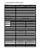
4.0 Specifications for Abrasive Saws Table 1 Model number Stock number Motor and Electricals Motor type Horsepower Phase Voltage Cycle Listed FLA (full load amps) Starting amps Running amps (no load) Motor speed Power cord Power plug installed Power transfer Pulley ratio Recommended circuit size 1 Sound emission without load 2 Cutting capacities 90 deg. Round 45 deg. 90 deg. Rectangle 45 deg. 90 deg. Square 45 deg.
1 subject to local and national electrical codes. The specified values are emission levels and are not necessarily to be seen as safe operating levels. As workplace conditions vary, this information is intended to allow the user to make a better estimation of the hazards and risks involved only.
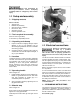
Read and understand all assembly instructions before attempting assembly. Failure to comply may cause serious injury. 5.0 Setup and assembly 5.1 Shipping contents Carton contents 1 1 1 1 1 1 Abrasive saw Material stop assembly Open-end wrench, 32/36mm Hex wrench, 8mm Operator’s manual Product registration card 5.2 Tools required for assembly 8mm hex wrench (provided) 21 and 24mm (or adjustable) wrench 5.3 Unpacking and cleanup 1. Inspect contents for shipping damage.
6.3 Conversion to 460V Grounded, cord-connected tools intended for use on a supply circuit having a nominal rating between 150-250 V inclusive: The Abrasive Saw is prewired for 230 volt. To change incoming leads for 460 volt operation: This tool is intended for use on a three-phase circuit. Make sure the tool is connected to an outlet having the same configuration as the plug (not provided). No adapter is available or should be used with this tool.
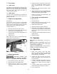
7.2 Vise action 4. Grasp blade with a gloved hand, and loosen hex nut on spindle with provided wrench. NOTE: Left-hand threads – turn clockwise to loosen. 5. Remove nut, outer flange and blade. Clean spindle and flange. 6. Install new blade, making sure that blade is flat against inner flange, and orientation matches any directional arrow printed on blade. 7. Tighten nut securely (counterclockwise), and reconnect guard linkage. 7.2.
6. Start blade by pressing trigger on handle grip. 7. Pull down operating lever to bring blade into work piece. You will manually control speed of downstroke. Do not exert excessive pressure, or damage to blade may result. 8. When cut is complete, release trigger and raise head. 10.0 User-maintenance 10.3 Additional servicing 10.1 Maintenance requirements Any additional servicing should be performed by authorized service personnel.
11.0 Troubleshooting AB-12/14 Abrasive Saws 11.1 Machine fault and operating problems Symptom Motor will not turn Possible Cause Correction* Low voltage. Check power line for proper voltage. Open circuit in motor or loose connection. Inspect all lead connections on motor for loose or open connections. Rotate Emergency Stop button to disengage.
11.2 Blade and cutting problems Symptom Possible Cause Rapid blade wear Feed speed too slow Broken blade Feed speed too high Correction The blade runs over the material without removing it: Increase pressure of blade into workpiece. Reduce pressure of blade into workpiece. Blade in contact with material before starting the cut Cuts not straight Feed speed too strong Make sure blade is clear of workpiece before starting machine. Reduce feed speed. Blade not perpendicular to workpiece.
12.1.
12.1.2 AB-12 Abrasive Saw – Parts List Index No Part No Description Size Qty 1 ................ TS-1504041 .............. Socket Head Cap Screw ......................................... M8x20 ........................... 4 2 ................ TS-1550061 .............. Flat Washer ............................................................. 8mm .............................. 6 3 ................ AB12-03 .................... Spring Pin ................................................................
Index No Part No Description Size Qty 56 .............. AB12-56 .................... Vise plate ................................................................. 2-3/8” x 3-1/8” ............... 1 57 .............. AB12-57 .................... Adjustable Handle ................................................... M10X30 ........................ 2 58 .............. TS-2361101 .............. Lock Washer ............................................................ 10mm ............................ 1 59 .....
Index No Part No Description Size Qty 116 ............ AB12-116 .................. Stop Block................................................................ ...................................... 1 117 ............ AB12-117 .................. Stop Rod .................................................................. ...................................... 1 118 ............ TS-154010 ................ Hex Nut .................................................................... M16 ......................
12.2.
12.2.2 AB-14 Abrasive Saw – Parts List Index No Part No Description Size Qty 1 ................ TS-1504041 .............. Socket Head Cap Screw ......................................... M8x20 ........................... 4 2 ................ TS-1550061 .............. Flat Washer ............................................................. 8mm .............................. 6 3 ................ AB12-03 .................... Spring pin ................................................................
Index No. Part No. Description Size Qty 56 .............. TS-1534052 .............. Machine Screw, Pan Head ...................................... M6x16 ........................... 4 57 .............. TS-1505011 .............. Socket Head Cap Screw ......................................... M10X16 ........................ 1 58 .............. AB14-58 .................... Support Saddle ........................................................ ...................................... 1 59 ..............
Index No. Part No. Description Size Qty 118 ............ AB14-118 .................. Handle Ball .............................................................. M8 ................................. 1 119 ............ TS-1514021 .............. Socket Head Flat Screw .......................................... M6x16 ........................... 2 120 ............ TS-154010 ................ Hex Nut .................................................................... M16 ............................... 1 121 .
13.
14.0 Warranty and service JET warrants every product it sells against manufacturers’ defects. If one of our tools needs service or repair, please contact Technical Service by calling 1-800-274-6846, 8AM to 5PM CST, Monday through Friday. Warranty Period The general warranty lasts for the time period specified in the literature included with your product or on the official JET branded website. • JET products carry a limited warranty which varies in duration based upon the product.
427 New Sanford Road LaVergne, Tennessee 37086 Phone: 800-274-6848 www.jettools.