
Use and Care Manual


10
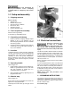
7.2 Vise action
7.2.1 AB-12 vise
The AB-12 vise is self-centering and has a cam
action lever for fast clamping. Turn handwheel (H,
Figure 7-1) to move vise jaw about 1/16-inch away
from work piece, then rotate cam lever (J)
counterclockwise to tighten.
7.2.2 AB-14 vise
The AB-14 vise is self-centering, with double vise
jaws driven by a lead screw. Clamp work piece by
rotating vise handle.
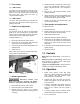
7.3 Depth of cut adjustment
See Figure 7-2.
The front stop screw (K, Figure 7-2) limits blade
depth of cut. The rear stop screw (L) limits return
motion of head. These stops have been set by the
manufacturer. If future adjustment is needed:
To adjust depth of cut:
1. Disconnect machine from power source.
2. Loosen hex nut on stop screw, and lower head
all the way for front stop adjustment.
3. Turn screw with wrench until blade bottoms out
at desired level.
4. Tighten hex nut.
Raise head all the way for rear stop adjustment,
using similar procedure as above.
Figure 7-2
7.4 Blade replacement
Disconnect machine from
power source before changing saw blades.
Failure to comply may result in serious injury!
1. Disconnect machine from power source.
2. Place saw head in fully raised position.
3. Remove screw (N, Figure 7-1) to release
linkage from blade guard, and rotate guard out
of the way.
4. Grasp blade with a gloved hand, and loosen
hex nut on spindle with provided wrench.
NOTE: Left-hand threads – turn clockwise to
loosen.
5. Remove nut, outer flange and blade. Clean
spindle and flange.
6. Install new blade, making sure that blade is flat
against inner flange, and orientation matches
any directional arrow printed on blade.
7. Tighten nut securely (counterclockwise), and
reconnect guard linkage.
7.5 Belt tension and replacement
To replace the belts:
1. Remove belt cover.
2. Slightly loosen two screws (P, Figure 7-2) and
slide motor forward to de-tension belts.
3. Replace both belts as a set.
4. Slide motor back and tighten screws (P).
5. Belt tension can be adjusted by loosening hex
nut on tension screw (M, Figure 7-2) and turning
tension screw which moves the motor mount
slide plate.
6. Lock tension screw setting by tightening hex nut
against casting.
7. Reinstall belt cover.
8.0 Controls
Main switch (on control box) – Turns power on
and off.
Emergency Stop (on control box) – Press to shut
down machine. To restart machine, rotate button
clockwise to disengage E-stop.
Trigger (on operating handle) – When pressed, it
activates micro-switch to start blade rotation.
9.0 Operation
1. Before using machine, check that safety
devices (e.g. blade guards) are in position and
work correctly and that personal safety
requirements are complied with.
2. Position work piece and close vise securely.
NOTE: Use supports, such as roller stands, for
long work pieces.
3. If mitering, adjust table accordingly and lock it
in position. If making a mitered cut, verify that
blade will not contact vise jaws; adjust if
needed.
4. If cutting multiple pieces to identical length,
adjust material stop and tighten in position.
5. Turn on main switch.