This .pdf document is bookmarked Operating Instructions and Parts Manual 8-3/4" Zip-Miter Bandsaw Model J-9225 JET 427 New Sanford Road LaVergne, Tennessee 37086 Ph.: 800-274-6848 www.jettools.com Part No.
Warranty and Service JET® warrants every product it sells against manufacturers’ defects. If one of our tools needs service or repair, please contact Technical Service by calling 1-800-274-6846, 8AM to 5PM CST, Monday through Friday. Warranty Period The general warranty lasts for the time period specified in the literature included with your product or on the official JET branded website. • JET products carry a limited warranty which varies in duration based upon the product.
Table of Contents Warranty and Service .................................................................................................................................... 2 Table of Contents .......................................................................................................................................... 3 Warning ......................................................................................................................................................... 4 Introduction...
Warning 1. Read and understand the entire owner's manual before attempting assembly or operation. 2. Read and understand the warnings posted on the machine and in this manual. Failure to comply with all of these warnings may cause serious injury. 3. Replace the warning labels if they become obscured or removed. 4. This bandsaw is designed and intended for use by properly trained and experienced personnel only.
26. Maintain tools with care. Keep blades sharp and clean for the best and safest performance. Follow instructions for lubricating and changing accessories. 27. Make sure the work piece is securely clamped in the vise. Never use your hand to hold the work piece. 28. Turn off the machine before cleaning. Use a brush or compressed air to remove chips or debris — do not use your hands. 29. Do not stand on the machine. Serious injury could occur if the machine tips over. 30.
Introduction This manual is provided by JET, covering the safe operation and maintenance procedures for a JET Model J-9225 zip-miter bandsaw. This manual contains instructions on installation, safety precautions, general operating procedures, maintenance instructions and parts breakdown. This machine has been designed and constructed to provide consistent, long-term operation if used in accordance with instructions set forth in this manual.
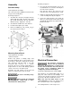
Saw Head Shipping Contents The saw head (Figure 1) consists of a drive motor, gearbox, blade wheels, blade guides and supports, control panel, blade tension mechanism, wire brush, and the saw blade. Contents of the Carton 1 1 1 1 1 1 1 1 Band Saw (not shown) Front Stand Panel (A) Rear Stand Panel (B) Left Stand Panel (C) Right Stand Panel (D) Bottom Plate (E) Operating Instructions/Parts List Warranty Card The drive wheel is installed on the output shaft of the gearbox.
Assembly Referring to Figure 3: Stand Assembly 1. The saw (A) and stand top (B) come as an assembled unit. Use a hoist to lift and place the saw onto the stand (C). Tools required for assembly: Note that the front of the saw faces the same direction as the flat panel of the stand. Two 1/2-inch wrenches (Note: A ratchet wrench may speed assembly time.) Referring to Figure 2: 2. Adjust the stand top (B) and stand (C) so the corner mounting holes (D) are aligned. 1.
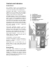
Controls and Indicators Control Panel The operating controls for the bandsaw are located on the control panel (Figure 4) and consist of the following controls and indicators: Emergency Stop Switch – by depressing this switch the user can quickly stop the machine when it is in operation; to restart, turn clockwise slightly to release then press Start switch Feed Rate Control – used in conjunction with the Feed Rate Start/Stop Control (see below); this knob is used to set the downward head speed that is appli
Blade Selection Operations The bandsaw is delivered with a saw blade that is adequate for a variety of cut-off jobs on a variety of common materials. A general-purpose blade is provided as standard equipment with the machine. After-market blades can be acquired for specific cutting jobs. Hydraulic Feed Control A coarse blade could be used for a solid steel bar, but a finer tooth blade would be used on a thin-wall steel tube.
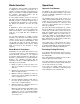
Setting the Work Stop Referring to Figure 5: The work stop is an accessory that is included with the JET J-9225 Bandsaw. It is used to set up the saw for making multiple cuts of the same length. Do not allow the blade to rest on the workpiece when the saw is not cutting. Installation 1. Insert the distance set rod (A) into the hole (B) at the front of the base as shown. 2. Secure by tightening the socket setscrew (C) with a 3mm hex wrench. Adjustment 3.
Miter Cuts Referring to Figure 7, the J-9225 band saw is capable of making angle cuts from 0–60º. The vise remains stationary while the saw head is adjusted as follows: 1. Place the saw head (F) in the raised position so the blade doesn't catch in the table slots. 2. Set the lock handle (A) to the unlock position as indicated by the arrows. 3. Using handles (B and C), rotate the saw head (F) to any desired angle within a range of 0º (square cut) to 60º, setting it to the scale (D) on the base. 4.
Bearing and Guide Block Adjustment Referring to Figure 10: Guide bearings and carbide guide blocks are located on either side of the saw blade and provide stability for the blade when the saw is in operation. These bearings rotate on an eccentric shaft so the distance from the blade can be adjusted for optimal performance. Guide blocks provide additional blade stability. Guide bearings and guide blocks are initially adjusted at the factory and should rarely require adjustment.
Blade Tension See Adjusting the proper Blade Tension on page 16. Limit Switch Adjustment Refer to Figure 12. The J-9225 bandsaw should shut off automatically when a cut is completed. If not, the limit switch probably needs to be adjusted as follows: Disconnect the cut-off saw from its electrical power source. 1. Place the saw in the lowered position to represent the completion of a cutting operation 2. Using a crosspoint screwdriver and 5/16" wrench, loosen two mounting screws (A). 3.
Maintenance Figure 13 Changing Blades 4. Pull the blade (E) off the drive wheel (F) and idler wheel (G) and out of the blade guides (H1, H2). Store the removed blade carefully before proceeding. Refer to Figure 13 except where specified otherwise. Use leather gloves when changing the saw blade to protect your hands from cuts and scratches. Use protective eye wear that meets ANSI Specification Z87.1 Installing New Blade 5.
Cleaning Coolant Clean off any preservative on machine surfaces. Change coolant on a frequency appropriate to the type of coolant being used. Oil based coolants can sour. Refer to the coolant supplier’s instructions for change frequency. After cleaning: 1. Coat machined surfaces of the cutoff saw with a medium consistency machine oil. Reapply the oil coating at least every six months. The general-purpose coolant is a mixture of water-soluble oil or synthetic based coolant and water.
Troubleshooting Fault Probable Cause Suggested remedy 1. Clamp work securely. 2. Check Machinist’s Handbook for speed/feed appropriate for the material being cut. 3. Check Machinist’s Handbook for Teeth too coarse for material. recommended blade type. 4. Adjust blade tension to the point Incorrect blade tension. where the blade just does not slip on the wheel. Saw blade is in contact with work- 5. Start the motor before placing the saw on the workpiece. piece before the saw is started. 6. Adjust guides.
Troubleshooting (cont.) Fault Probable Cause Suggested remedy Bad cuts (rough) 1. Blade speed too high for feed 1. Reduce blade speed and pressure. pressure. 2. Blade is too coarse. 2. Replace with finer blade. feed Blade is twisting 1. Blade is binding in the cut. 2. Blade tension too high Unusual wear on side/back of blade 1. Replace blade guides. 1. Blade guides worn 2. Adjust blade guide bearings. 2. Blade guide bearings not adjusted. 3. Blade guide bearing bracket is 3.
Saw Assembly – Parts Index No. Part No. Description Size Qty 1 ............... J-9225-01G .............. Body Frame.......................................................... .................................... 1 2 ............... J-9225-02G .............. Anchor Block ........................................................ .................................... 1 2A ............. J-9225-02A .............. Anchor Plate......................................................... .............................
Saw Assembly – Parts Index No. Part No. Description Size Qty 73 ............. TS-2361061 ............. Lock Washer ........................................................ M6 ............................... 4 74GA ........ 9225-74GA ............... Gear Box Assembly ............................................. .................................... 1 75 ............. TS-1551071 ............. Lock Washer ........................................................ M10 ............................. 4 76 ......
Saw Assembly – Parts Index No. Part No. Description Size Qty 172 ........... 9180-172 .................. Bearing Cover ...................................................... .................................... 1 173 ........... 9180-173 .................. Bearing ................................................................. ø30xø47x3.5 ............... 1 174 ........... 9180-174 .................. Vise Handle .......................................................... ................................
Saw Assembly – Parts Index No. Part No. Description Size Qty 232 ........... 9180-232 .................. Nut ........................................................................ .................................... 1 233 ........... 9225-233 .................. Swivel Lock Handle .............................................. .................................... 1 234 ........... TS-1550061 ............. Flat Washer .......................................................... M8 .......................
Saw Assembly Drawing (1 of 3) 23
Saw Assembly Drawing (2 of 3) 24
Saw Assembly Drawing (3 of 3) 25
Electrical Box Assembly – Parts Index No. Part No. Description Size Qty 215 ........... ................................. Electrical Control Box Assembly: 3Ph (Reference Only) .......................... 1 215-1 ........ 9180-215-1 ............... Magnetic Contactors ............................................ .................................... 1 215-2 ........ 9180-215-2 ............... Push Button Start Switch ..................................... .................................... 1 215-3 .......
Electrical Box Assembly 27
Wiring Diagram 427 New Sanford Road LaVergne, Tennessee 37086 Phone: 800-274-6848 www.jettools.