
Use and Care Manual

6
6.0 Uncrating and Cleanup
NOTE: Read and understand the entire manual
before attempting setup or operation.
1. Finish uncrating the saw and inspect for
damage. Should any have occurred, contact
your local distributor.
2. Remove all bolts attaching machine to
shipping base.
3. Leave packing material between vice clamps
and saw head intact until bandsaw has been
lifted to its final position.
4. Clean all rust protected surfaces with kerosene
or diesel oil to remove protective coating. Do
not use gasoline, paint thinner, mineral spirits,
etc. These may damage painted surfaces.
5. Lubricate all slideways with SAE 10W oil.
7.0 Installation
For best performance, the bandsaw should be
located on a solid and level foundation. Allow room
for servicing and for moving large stock around the
bandsaw when deciding a location for the machine.
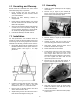
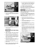
1. Using lifting straps that are isolated from the
bandsaw’s finished surfaces, place machine in
desired location. See Figure 1 for strap
placement.
Figure 1
2. Install four leveling bolts with lock nuts on both
sides of the base as shown in the parts
breakdown in sect. 14.1.1, items #2 and #3.
3. Place a level on the table surface and check
side to side and front to back.
4. Adjust leveling screws until machine is level in
both directions and tighten locking nuts.
8.0 Assembly
1. Unbolt the motor assembly from the shipping
crate bottom.
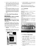
2. Remove nut (A, Figure 2) and washer (B,
Figure 2) from the motor support shaft. Note:
Picture shows motor already in place.
Figure 2
3. Remove shaft (C, Figure 2) from the motor
mount bracket.
4. Carefully lift motor and line up holes in the
motor mounting place and the motor bracket.
5. Slide motor support shaft into motor mount
bracket to hold the motor in place.
6. Fasten shaft with nut and washer.
7. Loosen strain relief nut on the motor junction
box. Remove the junction box cover. Insert
wire though strain relief and wire to the
terminal strip using the diagram on the junction
box cover. Tighten the strain relief nut and
replace the junction box cover.
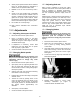
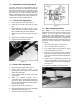
8. Remove two hex cap bolts and washers (A,
Figure 3) from the right side of the saw arm.
Figure 3
9. Slide belt cover (B, Figure 3) around pulley
shafts and attach to saw with two hex cap
bolts and two washers.
10. Lift motor and place v-belt around both pulleys.
Lower motor.