
Use and Care Manual

7
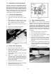
11. Tension the v-belt by pushing down on the
motor and tightening the lock handle on the
motor tilt plate. Correct tension is achieved
when finger pressure between the two pulleys
causes approximately a 1/2” deflection.
12. Close pulley cover door and fasten with lock
knob.
13. Fasten work stop rod (#241, sect. 14.1.1) to
saw bed (#11A) by inserting into bed and
turning clockwise until tight. Place work stop
bracket (#16) onto stop rod (#241) and tighten
lock handle (#20). Attach stop screw (#19) to
stop bracket (#16) with lock handle (#18) and
tighten.
9.0 Electrical Connections
All electrical connections
must be done by a qualified electrician. Failure
to comply may result in serious injury.
Disconnect machine from the
power source before changing any voltage
components. Failure to comply may cause
serious injury.
The MBS-1014W bandsaw is rated at 3HP, 3
phase 230/460V, prewired 230V; or 2HP, single
phase, 230V only. Confirm power available at the
saw’s location is the same as the saw is wired. To
switch the MBS-1014W from 230V to 460V, the
following items will have to be changed.
Main Motor – follow diagram inside junction
box cover.
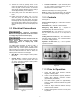
Coolant Pump – Remove access panel on
right side of saw, remove junction box cover
on pump, and follow diagram inside junction
box cover. See Figure 4.
Figure4
Control Transformer – Open electrical panel
on rear of base and switch primary wire on
transformer from 230V to 460V.
Machine must always be correctly grounded.
Note: the power cord end will have to be changed
to one that is rated 460V when changing voltage.
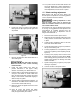
10.0 Controls
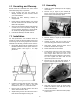
See Figure 5.
Power Indicator Light (A) – lit whenever machine
is running.
Start Button (B) – depress to start bandsaw.
Emergency Stop Button (C) – depress to
immediately stop all machine functions.
Coolant Switch (D) – turn arrow to “I” to turn on
flow of coolant. Turn arrow to “O” to stop flow of
coolant.
Cutting Pressure Control (E) – turn clockwise to
decrease cutting pressure. Turn counterclockwise
to increase cutting pressure.
Hydraulic On-Off Valve (F) – turns hydraulic
cylinder on and off.
Figure 5
11.0 Prior to Operation
1. Check that blade tooth direction matches
diagram on blade guides.
2. Check to see that blade is properly seated on
wheels after applying correction tension
(approximately 25,000 lbs.)
3. Set blade holder guides for approximately
0.003” to 0.005” clearance between the guides
and blade.
4. Check for slight clearance between back-up
rollers and back of blade.
5. Position blade guides as close to work piece
as possible.