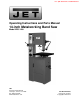
This .pdf document is bookmarked Operating Instructions and Parts Manual 14-inch Metalworking Band Saw Model VBS-1408 JET 427 New Sanford Road LaVergne, Tennessee 37086 Ph.: 800-274-6848 www.waltermeier.com Part No.
1.0 Warranty and Service JET warrants every product it sells against manufacturers’ defects. If one of our tools needs service or repair, please contact Technical Service by calling 1-800-274-6846, 8AM to 5PM CST, Monday through Friday. Warranty Period The general warranty lasts for the time period specified in the literature included with your product or on the official JET branded website. • JET products carry a limited warranty which varies in duration based upon the product.
2.0 Table of contents Section Page 1.0 Warranty and Service ..................................................................................................................................... 2 2.0 Table of contents............................................................................................................................................ 3 3.0 Safety warnings...................................................................................................................................
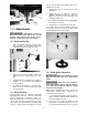
10. Do not operate this machine while tired or under the influence of drugs, alcohol or any medication. 11. Make certain the switch is in the OFF position before connecting the machine to the power supply. 3.0 Safety warnings 1. Read and understand the entire owner's manual before attempting assembly or operation. 2. Read and understand the warnings posted on the machine and in this manual. Failure to comply with all of these warnings may cause serious injury. 3.
25. Maintain tools with care. Keep saw blades sharp and clean for the best and safest performance. Follow instructions for lubricating and changing accessories. 33. Always wear leather gloves when handling saw blades. The operator should not wear gloves when operating the band saw. 34. Do not allow the saw blade to rest against the workpiece when the saw is not running. 26. Turn off the machine before cleaning. Use a brush or compressed air to remove chips or debris — do not use your bare hands. 35.
5.0 Specifications Model number ......................................................................................................................................... VBS-1408 Stock number .............................................................................................................................................. 414483 Blade speed .......................................................................................................................
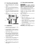
8.0 Electrical connections 6.0 Uncrating and assembly 1. Finish uncrating the band saw. Contact your distributor if any damage has occurred during shipping. 2. Remove any preservative with kerosene or diesel oil. Do not use gasoline, paint thinner, or any cellulose-based product, as these will damage painted surfaces. All electrical connections must be done by a qualified electrician. All adjustments or repairs must be done with machine disconnected from power source.
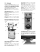
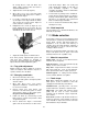
Anneal Button (K, Figure 3) – located on blade welder panel. Press and hold to anneal blade, release to stop. 9.0 Controls Variable Speed Handwheel (B, Figure 2) – Turn clockwise to increase speed and counterclockwise to decrease speed. CAUTION: Do not turn handwheel while machine is stopped. Adjust speed only when machine is running. Blade Clamp Pressure Knob (L, Figure 3) – located on blade welder panel. Sets pressure for different width blades.
next to, but not against, the flange at the rear. If adjustment is needed: Figure 5 1. Slightly loosen all four socket head cap screws (D, Figure 7). 2. Tighten two top set screws (E, Figure 7) slightly to shift blade toward front. Conversely, tighten two lower set screws (F, Figure 7) to shift blade toward rear. 3. Once blade is tracking properly, slightly tighten the other two set screws. 4. Tighten all four socket head cap screws (D).
far enough back to clear saw blade even during cutting operation when the blade is deflected toward the rear. 3. Tighten the two screws (G, Figure 8). 4. Open upper access door and rotate blade wheel by hand until weld portion of blade is between the two fingers. 5. Loosen two socket head cap screws (H, Figure 8) and adjust each finger toward the blade. They should not touch the blade. Adjust for 0.010” clearance on either side. 6. both wheel flanges. Make sure teeth point down toward table.
.3 Set type 5. 6. Straight Set – used for free cutting non-ferrous materials; i.e., aluminum, magnesium, plastics, and wood. 7. Wavy Set – used on materials of varying thickness (pipe, tubing, and structural shapes). Teeth are dull or improperly set. Upper guides are set too high off the workpiece. Faulty weld on blade. 12.0 Welder operation Raker Set – used in large cuts on thick plate and bar stock where finish of cut is not as important as speed. Wear eye protection while operating welder.
5. Insert opposite end of blade into right clamp. Position back edge of blade against back edge of right clamp. Then butt the end of blade against the other end of blade (the blade ends need to be in contact with each other). Tighten right clamp. 6. Set pressure selector switch (counterclockwise rotation) to the approximate setting required for the width of the blade being welded. Keep hands clear of weld area and clamp jaws during welding. 7. Figure 10 Press and hold weld button (Figure 12).
excess weld material using the grinder. Refer to section 12.5, Blade grinding. If blade is thicker at the weld than at the rest of the blade, using the blade may damage the guides. The following are variations of the general procedure, based upon blade type: 12.4.1 Carbon steel blades 1. Press and jog the annealing switch button until weld is a "dull cherry" to "cherry red" color. 2. Allow blade to cool slowly by decreasing jogging frequency. 12.4.2 Carbon steel hard back blades 1.
12.5 Blade grinding 13.0 Band saw operation Keep hands away from rotating grinding wheel. Failure to comply may cause serious injury. Always heed the indicator light – when glowing, it warns that the grinder motor is running. Consult section 9.0 for identification of the controls. Unlock the control panel using the provided key. Never operate band saw without blade and wheel covers in place and secured. After annealing, the blade must be ground to remove excess metal or flash from the weld.
13.3 Evaluating cutting efficiency Use a brush to loosen accumulated chips and debris. Use a shop vacuum to remove the debris. Make sure the chip brush on the lower band wheel is properly adjusted. The best way to determine whether a blade is cutting efficiently is to observe the chips formed by the cutting. • If chip formation is powdery, then the feed rate is too light, or blade is dull.
15.0 Troubleshooting 15.1 Operating problems Table 1 Trouble Probable Cause Remedy Blade has been improperly welded. Re-weld blade. See section 12.3 Blade not installed properly. Set guide inserts closer, and increase blade tension. Feeding workpiece too forcefully. Decrease feed rate. Incorrect choice of blade. Use proper width blade for radius or wavy line cutting. Blade tooth has improper set. File to proper set or replace blade. Inadequate blade tension. Increase tension.
15.2 Mechanical and electrical problems Table 2 Trouble Machine will not start/restart or repeatedly trips circuit breaker or blows fuses. Probable Cause No incoming power. Cord damaged. Overload automatic reset has not reset. Band Saw frequently trips. Building circuit breaker trips or fuse blows. Switch or motor failure (how to distinguish). Motor overheated. Machine will not start/restart or repeatedly trips circuit breaker or blows fuses (cont.) Motor failure. Miswiring of the unit.
15.3 Welded blade inspection Table 3 Trouble Probable Cause Remedy Weld is misaligned. Dirt or scale on clamp jaws or blade. Always keep jaws clean. Clean blade before welding. Blade ends not square. Before welding, grind cut edges of blade until they are square. Use the shear on the band saw for square cuts. Blade ends not correctly aligned when clamped in jaws. Align ends properly before clamping. Worn clamp jaws Replace clamp jaws. Clamp jaws not aligned correctly. Align jaws correctly.
15.4 Welder mechanical problems Table 4 Trouble Probable Cause Remedy Wire connection is poor; connecting point of welding switch is bad. Change switch, or grind the connecting port with a file. Transformer burned out. Change transformer, or rewire it. Blade has oil on it. Wipe off any oil. Blade ends have rust. Grind off rust. Welding switch is cutting off late. Screw welding switch connecting nut tighter. Welding press too weak. Rotate pressure selector knob accordingly.
16.
17.0 Typical Band Saw Operations Figure 17 18.0 Replacement Parts Replacement parts are listed on the following pages. To order parts or reach our service department, call 1800-274-6848 Monday through Friday, 8:00 a.m. to 5:00 p.m. CST. Having the Model Number and Serial Number of your machine available when you call will allow us to serve you quickly and accurately.
18.1.
18.1.
18.1.3 VBS-1408 Band Saw – Parts List Index No Part No Description Size Qty 1010 .......... VBS1408-1010 .......... Work Table .............................................................. ...................................... 1 1020 ......... VBS14-102 ................ Table Support Frame (s/n previous to 7011501) ..... ...................................... 1 .................. VBS14-1021 .............. Table Support Frame (s/n 7011501 and higher)...... ......................................
Index No Part No Description Size Qty 4180 .......... 4180 .......................... Air Nozzle Clip ......................................................... ...................................... 1 4190 .......... 4190 .......................... Air Tube (not shown) ............................................... ...................................... 1 5000 .......... VBS1408-5000G ....... Main Body ................................................................ gray ...............................
Index No Part No Description Size Qty 7451 .......... VBS16-7451 .............. Washer Tube ........................................................... ...................................... 1 7460 .......... VBS16-7460 .............. Pulley Shaft Arm ...................................................... ...................................... 1 .................. VBS1610-VP ............. Variable Pulley Assembly Complete ........................ ...................................... 1 7470 ..........
19.
427 New Sanford Road LaVergne, Tennessee 37086 Phone: 800-274-6848 www.jettools.