
Use and Care Manual

7
6.0
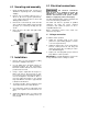
Uncrating and assembly
1. Finish uncrating the band saw. Contact your
distributor if any damage has occurred during
shipping.
2. Remove any preservative with kerosene or
diesel oil. Do not use gasoline, paint thinner,
or any cellulose-based product, as these will
damage painted surfaces.
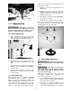
3. Remove two socket head cap screws from left
side of vertical column. Attach shear assembly
(A, Figure 1) to column by inserting hex cap
screws.
4. Place rip fence onto table and tighten with
locking knob.
Figure 1
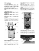
7.0 Installation
1. Remove three (3) nuts and washers holding
band saw to shipping crate bottom.
2. Use the lifting ring to lift band saw into its
permanent location. For best performance,
band saw should be bolted to floor after a level
position has been found.
3. Using a square, adjust table 90 degrees to
blade, both front to back and side to side.
Loosen the hex cap screws below the table to
move it and tighten to hold table in place. If
necessary, adjust the pointers to zero should
they read different once table is perpendicular
to blade in both directions.
4. To level the machine, place a machinist's level
on the table and observe in both directions.
5. Use metal shims under the appropriate hold
down screw. Tighten screw and recheck for
level.
6. Adjust with additional shims, as required, until
table is level when all mounting screws (or
nuts) are tight.
8.0 Electrical connections
All electrical connections
must be done by a qualified electrician. All
adjustments or repairs must be done with
machine disconnected from power source.
Failure to comply may cause serious injury.
The VBS-1408 Band Saw is rated at 115/230V and
comes from the factory prewired 115V.
The band saw must be grounded. A qualified
electrician can make the proper electrical
connections and confirm the power on site is
compatible with the saw.
Before connecting to power source, make sure
switch is in off position.
8.1 Voltage conversion
To switch to 230V operation:
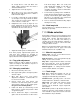
1. Switch the incoming leads in the motor
junction box (follow wiring diagram on inside
cover of motor junction box).
2. Switch the jumper wires on the circuit board.
Remove control panel from saw body and
change the jumper wires according to section
19.0, Electrical diagram.
3. Replace the 115V plug with a proper UL-listed
plug suitable for 230V operation.
IMPORTANT: Consult the diagrams in section 19.0
for any clarification of these changes to 230V.