
Use and Care Manual

8
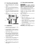
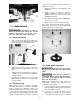
9.0 Controls
Variable Speed Handwheel (B, Figure 2) – Turn
clockwise to increase speed and counterclockwise
to decrease speed. CAUTION: Do not turn
handwheel while machine is stopped. Adjust
speed only when machine is running.
Upper Blade Guide Lock Knob (C, Figure 2) –
Turn counterclockwise to loosen and clockwise to
tighten.
Work Lamp Switch (D, Figure 2) – on top of lamp
shade; turns lamp on and off.
Main Motor Start Switch (E, Figure 2) – Press to
start band saw.
Main Motor Stop Switch (F, Figure 2) – Press to
stop band saw.
Shear Lever (G, Figure 2) – UP position allows
insertion of blade end into shear. Pull lever DOWN
to cut blade.
Blade Tension Handwheel (H, Figure 2) – located
on underside of upper frame. Turn clockwise to
tension blade; counterclockwise to release tension
on blade.
Figure 2
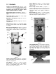
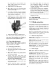
Grinder Toggle Switch (I, Figure 3) – located on
blade welder panel. Flip switch up to start grinder;
flip down to stop grinder.
Weld Button (J, Figure 3) – located on blade
welder panel. Press and hold to start welding.
Shuts off automatically when weld is done.
Release when weld is completed.
Anneal Button (K, Figure 3) – located on blade
welder panel. Press and hold to anneal blade,
release to stop.
Blade Clamp Pressure Knob (L, Figure 3) –
located on blade welder panel. Sets pressure for
different width blades. Turn counterclockwise to
bring blade clamps closer together, clockwise to
separate.
Blade Clamps (M, Figure 3) – located on blade
welder panel. DOWN position allows insertion of
blade into clamp. UP position locks blade.
Figure 3
Table Tilt Mechanism – located under work table.
To tilt table left or right, loosen two socket head
cap screws (N, Figure 4) at rear of mechanism. To
level table front to back, loosen four socket head
cap screws (O, Figure 5) on either side of
mechanism.
Figure 4