
Use and Care Manual

9
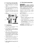
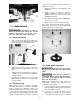
Figure 5
10.0 Adjustments
All adjustments or repairs to
machine must be done with power off and
machine disconnected from power source.
Failure to comply may cause serious injury.
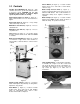
10.1 Blade tensioning
1. Raise upper blade guide by loosening lock
knob (A, Figure 6) and lifting blade guide
handle (B, Figure 6) to its highest position.
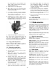
Figure 6
2. Apply finger pressure to blade. Travel from
vertical should be approximately 3/8" each
way.
3. To tighten blade, turn handwheel (C, Figure 6)
clockwise. To loosen blade, turn handwheel
counterclockwise.
4. Use blade tension indicator as reference only.
Blade should be tensioned using the finger
pressure method.
10.2 Blade tracking
Blade tracking may be required periodically
depending upon blade size and tension. The blade
must be tensioned as outlined in section 10.1
Blade tensioning. Disconnect machine from power
source and open upper blade wheel door. Turn
upper blade wheel by hand while observing blade
position on upper blade wheel. Blade should run
next to, but not against, the flange at the rear. If
adjustment is needed:
1. Slightly loosen all four socket head cap screws
(D, Figure 7).
2. Tighten two top set screws (E, Figure 7)
slightly to shift blade toward front. Conversely,
tighten two lower set screws (F, Figure 7) to
shift blade toward rear.
3. Once blade is tracking properly, slightly tighten
the other two set screws.
4. Tighten all four socket head cap screws (D).
Note: Upper and lower blade guides should be
moved away and left loose from the blade while
tracking adjustments are being made.
Figure 7
10.3 Blade guide adjustment
Blade guides must be properly
adjusted or damage may occur to blade and/or
guides.
Guard has been removed to
show detail. Always operate saw with guard in
place and properly adjusted. Failure to comply
may cause serious injury.
Blade guide adjustment has been set by the
manufacturer. Should future adjustment be
needed, proceed as follows.
1. Loosen upper blade guide lock knob and raise
guide assembly to half-way between table and
head, then tighten lock knob
2. Loosen two set screws (G, Figure 8) and
adjust guide so that blade guides are in back
of saw teeth. Blade guides must be adjusted