This .pdf document is bookmarked Operating Instructions and Parts Manual 8-inch Grinder with Belt Sander Models IBGB-248/248VS/436/436VS Variable speed model IBGB-436VS shown for models with serial no. 19120001 and higher. JET 427 New Sanford Road LaVergne, Tennessee 37086 Ph.: 800-274-6848 www.jettools.com Part No.
12. Make certain the switch is in the OFF position before connecting the machine to the power supply. 13. Make certain the machine is properly grounded. 1.0 IMPORTANT SAFETY INSTRUCTIONS 14. Make all machine adjustments or maintenance with the machine unplugged from the power source. 15. Remove adjusting keys and wrenches. Form a habit of checking to see that keys and adjusting wrenches are removed from the machine before turning it on. WARNING – To reduce risk of injury: 1.
40. Allow abrasive wheel to reach full RPM before starting the grinding operation. 27. Never leave grinder running unattended. Turn power off and do not leave machine until wheel comes to a complete stop. 41. Do not crowd the work so that the wheel slows. 28. Remove loose items and unnecessary work pieces from the area before starting the grinder. 42. Tool rests should be adjusted to approximately 1/16” from wheel surface. 29. Don’t use in dangerous environment.
2.0 Table of contents Section Page 1.0 IMPORTANT SAFETY INSTRUCTIONS ....................................................................................................... 2 2.0 Table of contents ............................................................................................................................................ 4 3.0 About this manual .......................................................................................................................................... 5 4.
14.1 Wiring diagram for IBGB-248 and IBGB-436 ......................................................................................... 34 14.2 Wiring diagram for IBGB-248VS and IBGB-436VS ................................................................................ 34 15.0 Warranty and service ................................................................................................................................. 35 3.
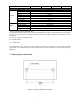
4.0 Specifications Table 1 Stock number Model number Motor and Electricals Type Motor Horsepower Phase Voltage Cycle Listed FLA (full load amps) Starting capacitor Running capacitor Input power required On/off switch 577248 IBGB-248VS 578248 IBGB-248 Shipping dimensions (L x W x H) 578436 IBGB-436 Induction, Induction, Induction, capacitor start, capacitor start, with inverter centrifugal switch centrifugal switch 1HP single 115/230V, prewired 115V 60 Hz 7 / 3.5 A 11 / 5.5 A 7 / 3.5 A 11 / 5.
IBGB-248VS Main materials Motor housing End cover Base Tool rest Grinder Inner wheel guard Outer wheel guard Flange washer Eye shield Belt table Belt table bracket Sander Tool rest Tool rest bracket IBGB-248 IBGB-436VS IBGB-436 Sheet metal Aluminum (Grinder side) / Cast iron (Belt sander side) Cast iron Cast iron Cast iron Aluminum Cast iron Polycarbonate Cast iron Sheet metal Sheet metal Sheet metal 1 subject to local and national electrical codes.
4.
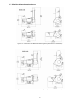
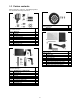
5.0 Carton contents Refer to Figures 5-1 thru 5-4. The identifying letters are used in the assembly instructions. Figure 5-1 Eye shield hardware Part no. IBG8-100 A Spark guard B Lock knob C Flat washer, 1/4" D Eye shield bracket E Eye shield plate F Hex cap screw, 3/8 x 5/8" G Hex cap screw, 3/8 x 1/2" H Truss head screw, 3/16 x 1/2” J Flat washers 3/8” Figure 5-3 Dust port package Dust port Truss head screw 3/16 x 3/8 Qty.
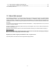
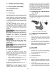
as it helps keep the circuit board at an acceptable temperature. These holes should not be obstructed. If the rubber pads are removed for mounting to a table, allow an opening in the table below the grinder for air circulation. However, it is recommended the rubber pads be left on, as they allow air circulation as well as vibration dampening. 6.0 Setup and assembly 6.1 Tools required for assembly Cross-point (Phillips) screwdriver 14mm (or adjustable) wrench 3mm hex wrench 6mm hex wrench 6.
must be readjusted to maintain a maximum 1/16" clearance. Figure 6-4: installing handles 6.9 Stand-off 1. Install stand-off (shown installed in Figure 8-2) into threaded hole in back of sanding arm. 2. Loosen screw (A, Figure 6-5) with 6mm hex wrench and lower sanding arm to horizontal position. 3. Turn stand-off in or out as needed until sanding arm is level with workbench. 4. Tighten hex nut against sanding arm to secure setting of stand-off. 6.
7.0 Electrical connections Check with a qualified electrician or service personnel if the grounding instructions are not completely understood, or if in doubt as to whether the tool is properly grounded. Failure to comply may cause serious or fatal injury. Electrical connections should be made by a qualified electrician in compliance with all relevant codes. This tool must be properly grounded.
Make sure your extension cord is in good condition, and is heavy enough to carry the current your product will draw. An undersized cord will cause a drop in line voltage resulting in loss of power and overheating. Table 2 shows the correct size to use depending on cord length and nameplate ampere rating. If in doubt, use the next heavier gage. The smaller the gage number (AWG), the heavier the cord.
4. Contour sanding (horizontal position) – Contoured workpieces can be sanded over the drive wheel. Open end cover, adjust tool rest and tighten in place. Turn knob (F) while moving the belt until belt completely covers drive wheel and stays centered. Turn handle clockwise to shift belt to the right (away from grinder), counterclockwise to shift belt to the left (toward grinder). NOTE: This adjustment is sensitive, turn handle in small increments and allow belt to respond to changes. 5.
9.2 Precautions 9.2.1 Wheel grinding 1. Before starting grinder, turn grinding wheel by hand to verify that it is clear of obstruction and turns freely. The tool rest and spark guard should not touch the wheel. 2. Keep tool rest and spark guard to within 1/16" of grinding wheel. 3. Turn on grinder and allow it to reach full running speed before starting to grind. 4. Adjust the eye shield as needed. 5.
10.4 Changing wheels 9. The JET bench grinder comes equipped with a general purpose grinding wheel. Wheels vary according to types of abrasive, hardness, grit size, and structure. Contact your local distributor for the proper grinding wheel or wire wheel brush for your application. Install inner flange, wheel (F), outer flange (E) and nut (D) on the shaft. Tighten nut counterclockwise. Do not overtighten nut; this may cause the wheel to crack. Maximum safe torque on nut is 20 lbf•ft (270 kgf•cm). 10.
4. 10.7 Wire wheel brushes Continue this combination of flange movements until the wobble is eliminated. Wire brushing (not provided) is a fast way to remove rust scale, burrs, and paint from metal. Use coarse wire brushes for hard cleaning jobs. Use fine wire brushes for polishing and finish work. When the brush tips become dull, reverse the brush on the grinder. If required, a shim made of paper or card stock may be placed between flange and wheel side. 10.
11.0 Optional accessories These accessory items, purchased separately, will accommodate your JET bench grinder. Contact your dealer to order, or call JET at the phone number on the cover. 578172 Stand for Grinders 578173 Deluxe Stand for Grinders 578100 Flexible 3W LED Lamp (includes two 1/4 x 3/8 mounting screws) The following accessories are for using the Grinder with the JET #414800 (JDCS-505) Dust Collection Stand: 414825 Reducer, 3 in. to 2.5 in. 414811 0.6M Hose, Heat Resistant, ø2.5 x 24.4 in.
12.0 Troubleshooting IBGB series Sander/Grinder 12.1 General mechanical and electrical problems Some corrections may require a qualified electrician. Symptom Possible Cause Correction Motor will not start. No incoming power. Verify that plug is properly inserted into receptacle. If so, check main panel for tripped breaker or blown fuse. Non-variable speed models: Safety key is missing. Make sure safety key is inserted. Wheel(s) cannot rotate because of obstruction.
Symptom Possible Cause Correction Low voltage. Correct the low voltage conditions. Motor stalls (cont.) Incorrect fuses or circuit breakers in power line. Install correct fuses or circuit breakers. Motor slows. Motor overloaded. Reduce load to motor; do not press so hard. Low line voltage. Check power line for proper voltage. Loose connections. Inspect connections. Motor overload. Reduce load to motor; do not press so hard.
13.0 Replacement Parts Replacement parts are listed on the following pages. To order parts or reach our service department, call 1-800274-6848 Monday through Friday, 8:00 a.m. to 5:00 p.m. CST. Having the Model Number and Serial Number of your machine available when you call will allow us to serve you quickly and accurately. Non-proprietary parts, such as fasteners, can be found at local hardware stores, or may be ordered from JET.
13.1.
13.1.2 IBGB-248 Sander/Grinder – Parts List Index No Part No Description Size Qty 1 ................ IBGB248-01 .............. Motor Housing w/ Stator .......................................... ...................................... 1 2 ................ IBGB248-02 .............. Rotor ........................................................................ ...................................... 1 3 ................ IBGB248-03 .............. End Cover .....................................................
Index No Part No Description Size Qty 60 .............. IBGB248-60 .............. Knob ........................................................................ 1/4” ................................ 4 61 .............. IBGB248-61 .............. Dust Port .................................................................. Dia. 2” ........................... 1 62 .............. F002176 .................... External Tooth Lock Washer * ................................. M8 .................................
13.2.
13.2.2 IBGB-248VS Sander/Grinder – Parts List Index No Part No Description Size Qty 1 ................ IBGB248VS-01.......... Motor Housing w/ Stator .......................................... ...................................... 1 2 ................ IBGB248VS-02.......... Rotor ........................................................................ ...................................... 1 3 ................ IBGB248-03 .............. End Cover .........................................................
Index No Part No Description Size Qty 61 .............. IBGB248-61 .............. Dust Port .................................................................. Dia. 2” ........................... 1 62 .............. F002176 .................... External Tooth Lock Washer * ................................. M8 ................................. 1 63 .............. TS-1550041 .............. Flat Washer ............................................................. M6 ................................. 2 64 ..
13.3.
13.3.2 IBGB-436 Sander/Grinder – Parts List Index No Part No Description Size Qty 1 ................ IBGB248-01 .............. Motor Housing w/ Stator .......................................... ...................................... 1 2 ................ IBGB436-02 .............. Rotor ........................................................................ ...................................... 1 3 ................ IBGB248-03 .............. End Cover .....................................................
Index No Part No Description Size Qty 60 .............. IBGB248-60 .............. Knob ........................................................................ 1/4” ................................ 4 61 .............. IBGB248-61 .............. Dust Port .................................................................. Dia. 2” ........................... 1 62 .............. F002176 .................... External Tooth Lock Washer * ................................. M8 .................................
13.4.
13.4.2 IBGB-436VS Sander/Grinder – Parts List Index No Part No Description Size Qty 1 ................ IBGB248VS-01.......... Motor Housing w/ Stator .......................................... ...................................... 1 2 ................ IBGB436VS-02.......... Rotor ........................................................................ ...................................... 1 3 ................ IBGB248-03 .............. End Cover .........................................................
Index No Part No Description Size Qty 61 .............. IBGB248-61 .............. Dust Port .................................................................. Dia. 2” ........................... 1 62 .............. F002176 .................... External Tooth Lock Washer * ................................. M8 ................................. 1 63 .............. TS-1550041 .............. Flat Washer ............................................................. M6 ................................. 2 64 ..
14.0 Electrical Connections 14.1 Wiring diagram for IBGB-248 and IBGB-436 S Black 1 Red 3 115V Input Power 35uf/250VAC C Gray 2 200MDF/125VAC M C Yellow 4 Green G S 1 Black 2 Gray 3 Red 4 Yellow 35uf/250VAC 230V Input Power C 200MDF/125VAC M C Green G 14.
15.0 Warranty and service JET warrants every product it sells against manufacturers’ defects. If one of our tools needs service or repair, please contact Technical Service by calling 1-800-274-6846, 8AM to 5PM CST, Monday through Friday. Warranty Period The general warranty lasts for the time period specified in the literature included with your product or on the official JET branded website. JET products carry a limited warranty which varies in duration based upon the product.
427 New Sanford Road LaVergne, Tennessee 37086 Phone: 800-274-6848 www.jettools.