
Use and Care Manual


10
6.0 Setup and assembly
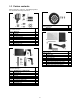
6.1 Tools required for assembly
Cross-point (Phillips) screwdriver
14mm (or adjustable) wrench
3mm hex wrench
6mm hex wrench
6.2 Unpacking
Separate all parts from the packing material. Check
each part against sect. 5.0, Carton contents, and
make certain that all items are accounted for.
(Check whether any parts have been pre-mounted
to the grinder.) Notify your dealer or JET if missing
or damaged items are discovered. Do not discard
any packing material until grinder is assembled and
operating properly.
The IBGB Grinder/Belt Sander requires only
minimal assembly. Additional tools may be needed
for fastening the grinder to a workbench or stand.
For your safety, do not plug the grinder into a power
source until all assembly and adjustments are
complete.
Make sure that bench grinder is
unplugged and power switch is in OFF position.
Do not plug in the grinder to power until it is
inspected for shipping damage, fully
assembled, and moved to its permanent
location. Failure to comply may cause serious
injury.
Do not operate this machine
without all guards and shields in place and in
working order. Failure to comply may cause
serious injury.
Chipped or cracked wheels can
break up and cause serious damage to the
grinder and/or severe injury to the operator.
Regularly inspect wheels for damage.
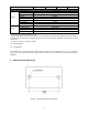
6.3 Securing the grinder
To prevent the machine from moving during
operation, it should be securely mounted to a work
bench or grinder stand. Fasteners for mounting are
not included with the grinder.
1. Align mounting holes on grinder with predrilled
holes in bench or grinder stand. Figure 4-1
shows hole centers for mounting.
2. Insert M10 (or 3/8”) bolts through the holes and
secure with washers and nuts.
An optional JET pedestal stand (not included) is
available for your grinder. See sect. 11.0.
IMPORTANT: The grinder’s base plate contains
ventilation holes for heat dissipation. This is
especially important on the variable speed models,
as it helps keep the circuit board at an acceptable
temperature. These holes should not be obstructed.
If the rubber pads are removed for mounting to a
table, allow an opening in the table below the grinder
for air circulation. However, it is recommended the
rubber pads be left on, as they allow air circulation
as well as vibration dampening.
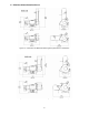
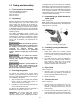
6.4 Assembling eye shield bracket to
spark guard
Refer to Figure 6-1.
Note: Spark guard (A) and eye shield bracket (D)
are marked L for left side assembly. Assemble these
using Figure 6-1 as a guide.
Figure 6-1: bracket to spark guard
6.5 Installing spark guard/bracket
Refer to Figure 6-2.
1. Install spark guard and mounting bracket
assembly to the left wheel housing with two 3/8
x 1/2” hex cap screws (G) and two 3/8" flat
washers (J).
2. The spark guard (A
1
) should be adjusted to
within 1/16" of the grinding wheel surface or
other accessory being used. As the wheel
wears down, the spark guard must be re-
adjusted to maintain this 1/16" distance.
6.6 Eye shield
Refer to Figure 6-2.
1. Insert two 3/16” x 1/2” truss head screws (H)
through bracket, eye shield (V), and plate (E)
which contains threaded mounting holes.
2. Tighten screws (H).
6.7 Grinder tool rest
Refer to Figure 6-2.
1. Install tool rest (Y) by inserting two 3/8" x 3/4"
hex cap screws (F) through two 3/8" flat
washers (J), through the tool rest (Y), into the
wheel housing.
2. The tool rest should be adjusted to within 1/16"
of the grinding wheel or other accessories being
used. As the wheel wears down, the tool rest