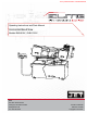
This .pdf document is bookmarked Operating Instructions and Parts Manual Horizontal Band Saw Models EHB-916V | EHB-1018V JET® 427 New Sanford Road LaVergne, Tennessee 37086 www.jettools.com Ph.: 855-336-4032 Part No.
1.0 WARRANTY AND SERVICE JET® warrants every product it sells against manufacturers’ defects. If one of our tools needs service or repair, please contact Technical Service by calling 1-855-336-4032, 8AM to 5PM CST, Monday through Friday. WARRANTY PERIOD The general warranty lasts for the time period specified in the literature included with your product or on the official JET branded website, jettools.com.
MORE INFORMATION JET® is constantly adding new products. For complete, up-to-date product information, check with your local distributor or visit the JET website, jettools.com. HOW STATE LAW APPLIES This warranty gives you specific legal rights, subject to applicable state law. LIMITATIONS ON THIS WARRANTY JET LIMITS ALL IMPLIED WARRANTIES TO THE PERIOD OF THE LIMITED WARRANTY FOR EACH PRODUCT.
2.0 TABLE OF CONTENTS 1.0 WARRANTY AND SERVICE .........................................................................................................................................2 2.0 TABLE OF CONTENTS .................................................................................................................................................4 3.0 SAFETY WARNINGS .........................................................................................................................................
10. 11. 12. 13. 14. 15. 16. 17. 18. 19. 20. 21. 22. 23. 24. 25. 26. 27. 28. 29. 30. 31. 32. 33. 34. 35. 36. Make certain the switch is in the OFF position before connecting the machine to the power supply. Make certain the machine is properly grounded. Make all machine adjustments or maintenance with the machine unplugged from the power source. Remove adjusting keys and wrenches. Form a habit of checking to see that keys and adjusting wrenches are removed from the machine before turning it on.
Familiarize yourself with the following safety notices used in this manual: This means that if precautions are not heeded, it may result in minor injury and/or possible machine damage. This means that if precautions are not heeded, it may result in serious or even fatal injury. 4.0 INTRODUCTION This manual is provided by JET® covering the safe operation and maintenance procedures for a JET Model EHB-916V and EHB-1018V.
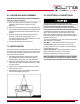
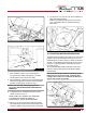
6.0 UNCRATING AND ASSEMBLY 8.0 ELECTRICAL CONNECTIONS Note: Read and understand the entire manual before attempting setup or operation. 1. Finish uncrating the saw and inspect for damage. Should any have occurred, contact your local distributor. 2. Remove all bolts attaching machine to shipping base. 3. Leave packing material between vise clamps and saw head intact until band saw has been lifted to its final position. 4.
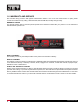
9.0 CONTROLS 11.0 PRIOR TO OPERATION Refer to Figure 2. 1. Check that blade tooth direction matches diagram on blade guides. Power Indicator Light (A) – lit whenever machine is running. If the bulb is out, lamp will not light, but machine may still have power. 2. Check to see that blade is properly seated on wheels after applying correct tension (approximately 25,000 lbs.). 3. Set blade holder guides for approximately .003” to .005” clearance between guides and blade. 4.
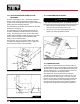
11. Jog the power “on” and “off” to be sure the blade is in place and tracking properly. If blade is not tracking properly refer to the section 12.11 “Adjust Blade Tension and Blade Tracking Adjustment”. A B C A Fig. 3 Fig. 5 12.2 ADJUSTING BLADE GUIDE BRACKETS E F D Fig. 4 7. Place the blade in place on the wheels (A) and through the upper blade guard (B) Fig. 3 is shown with the wheel covers removed for clarity. 8.
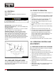
12.3 ADJUSTING BLADE GUIDE ROLLER BEARINGS 12.4 CHANGING BLADE SPEED The back of the blade (A) Fig. 7, should ride against the back-up support bearing (B) which is positioned at an angle so as to provide greater bearing support, eliminating bearing wear and extending blade life. The saw blade (A) should also ride between the two roller bearings (C) and (D) Fig. 7. The rear bearing (C) on the left hand blade guide can be easily adjusted to suit blade thickness by loosening nut (E).
A A D B B C C Fig. 10 12.6 BOW WEIGHT ADJUSTMENT Bow weight is one of the most important adjustments of the saw. If the bow weight is not set properly, one can expect poor performance, crooked cuts, tooth stripping, stalling, and the blade popping off the blade wheels. The hydraulic feed rate unit will not compensate for improper bow weight. Bow weight has been set at the factory and should not need any adjustment. If adjustment becomes necessary: Fig. 11 12.8 SETTING UP THE MACHINE FOR OPERATION 1.
.9 AUTOMATIC SHUT-OFF The machine and any accessories which are wired into the electrical system are controlled by the start-stop buttons. The machine will automatically shut off when the cut is completed. The lever (A) Fig. 13, for the automatic shut-off contacts the top of the hydraulic cylinder (B) and shuts off the machine. LUBRICATION OF HYDRAULIC SYSTEM A If it is necessary to fill the hydraulic cylinder with oil, proceed as follows: 1.
.0 MAINTENANCE Before doing maintenance on the machine, disconnect it from the electrical supply by pulling out the plug or switching off the main switch! Failure to comply may cause serious injury. Keep the band saw and the motor clean. If the power cord is worn, cut, or damaged in any way, have it replaced immediately. 15.0 REPLACEMENT PARTS — EHB-916V and EHB-1018V Replacement parts are listed on the following pages.
SAW STAND AND BED ASSEMBLY — EHB-916V 14 Horizontal Band Saw
PARTS LIST SAW STAND AND BED — EHB-916V Index No. 1 2 3 4 5 6 7 8 9 10 11 12 13 14 15 16 17 18 19 20 21 22 23 Part No.
Index No. 44 45 46 47 48 49 50 51 52 53 54 54-1 55 56 56-1 57 57-1 58 59 60 61 62 63 64 65 66 67 68 69 70 71 72 72-1 72-2 73 74 75 76 77 78 78-1 78-2 79 79-1 79-2 79-3 16 Part No.
Index No. 79-4 79-5 80 81 82 83 84 85 86 87 88 89 90 90-1 Part No.
SAW ARM ASSEMBLY — EHB-916V 18 Horizontal Band Saw
PARTS LIST SAW ARM — EHB-916V Index No. 1 1-1 2 3 4 5 6 7 8 8-1 9 10 11 12 13 14 15 16 17 18 19 20 21 22 23 24 25 26 28 29 31 32 33 34 35 35-1 Part No.
Index No. 45 46 47 48 49 50 51 52 55 56 57 58 68 68-1 70 71 73 74 75 76 77 78 79 80 81 82 83 84 85 86 86-1 86-2 87 88 89 90 Part No.
Index No. 100 103 109 110 111 112 113 114 118 119 121 122 123 124 125 126 127 128 129 130 131 132 133 134 134-1 135 136 137 138 139 140 141 142 144 144-1 145 146 147 148 149 150 151 153 154 154-1 154-2 155 Part No.
Index No. 156 156-1 156-2 157 158 159 160 161 165 166 167 168 169 22 Part No. EHB916V-156 EHB916V-156-1 TS-0680011 EHB916V-157 EHB916V-158 TS-0680041 EHB916V-160 EHB916V-161 EHB916V-165 EHB916V-166 EHB916V-167 TS-081F051 891095 Description Blade Cover Screw Washer Blade Cover Special Knob Flat Washer Hex Head Screw Bracket Round Head Screw Cover L.H Handle Phillips Screw Blade Size 3/8" 3/8 ×16 ×3/4" 3/16 ×3/8" 1/4"-20 × 3/4" 1"x 0.035" x 128-1/2" (4/6T) Qty.
SAW STAND AND BED ASSEMBLY — EHB-1018V EHB-916V | EHB-1018V 23
SAW STAND AND BED — EHB-1018V Index No. 1 2 3 4 5 6 7 8 9 10 11 12 13 14 15 16 17 18 19 20 21 22 23 Part No.
Index No. 43 44 45 46 47 48 49 50 51 52 53 54 55 56 56-1 57 57-1 58 59 60 61 Part No.
Index No. 79-4 79-5 80 81 82 83 84 85 86 87 88 89 90 91 91-1 26 Part No.
SAW ARM ASSEMBLY — EHB-1018V EHB-916V | EHB-1018V 27
PARTS LIST SAW ARM — EHB-1018V 28 Index No. 1 1-1 2 3 4 5 6 7 8 8-1 9 10 11 12 13 14 15 16 17 18 19 20 21 22 23 24 25 26 28 29 31 32 33 34 35 35-1 Part No.
Index No. 45 46 47 48 49 50 51 52 55 56 57 58 68 68-1 70 71 73 74 75 76 77 78 79 80 81 82 83 84 85 86 86-1 86-2 87 88 89 90 Part No.
Index No. 100 103 109 110 111 112 113 114 118 119 121 122 123 126 127 128 129 130 131 132 133 134 134-1 135 136 137 138 139 140 141 142 144 144-1 145 146 147 148 149 150 151 153 154 154-1 154-2 155 156 156-1 156-2 157 158 159 30 Part No.
Index No. 160 161 165 166 167 168 169 Part No. EHB1018V-160 EHB1018V-161 EHB916V-165 EHB-916V-166 EHB916V-167 TS-081F051 891096 EHB-916V | EHB-1018V Description Hex Head Screw Bracket Round Head Screw Cover L.H Handle Phillips Screw Blade Size 3/8”-16 x 3/4” 3/16 ×3/8" 1/4"-20 × 3/4" 1" x 0.035" x 132-1/2"( 4/6T) Qty.
ELECTRIC ASSEMBLY — EHB-916V PARTS LIST ELECTRICAL BOX — EHB-916V Index No. 308-1 308-2 308-2-1 308-3 308-4 308-5 308-6 308-7 308-8 308-9 308-10 308-11 308-12 308-13 308-13-1 308-15 308-16 308-19 32 Part No.
ELECTRIC ASSEMBLY — EHB-1018V PARTS LIST ELECTRICAL BOX — EHB-1018V Index No. 308-1 308-2 308-2-1 308-3 308-4 308-5 308-6 308-7 308-8 308-9 308-10 308-11 308-12 308-13 308-13-1 308-15 308-16 308-19 Part No.
16.
NOTES EHB-916V | EHB-1018V 35
NOTES 36 Horizontal Band Saw