
Use and Care Manual

10
Horizontal Band Saw
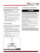
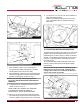
12.3 ADJUSTING BLADE GUIDE ROLLER
BEARINGS
The back of the blade (A) Fig. 7, should ride against the
back-up support bearing (B) which is positioned at an
angle so as to provide greater bearing support, eliminating
bearing wear and extending blade life.
The saw blade (A) should also ride between the two roller
bearings (C) and (D) Fig. 7.
The rear bearing (C) on the left hand blade guide can
be easily adjusted to suit blade thickness by loosening
nut (E). The bearing (C) is on an eccentric shaft which
enables it to be adjusted for blade thickness in the same
manner with the exception that the adjustable roller
bearing is in the forward position.
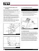
Part (F) shown Fig. 8 is a tungsten carbide block, after
completing the adjustments shown in Fig. 7, tighten the
Part (F) onto the surface of the saw blade.
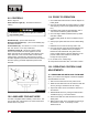
12.4 CHANGING BLADE SPEED
1. Raise cutting head approximately six inches above
work piece and turn feed rate knob to zero.
2. Turn power on and turn speed adjuster knob (as in
Figure 9) to match appropriate material.
12.5 OPERATING VISE
The workpiece is placed between the vise jaws with the
required amount to be cut-off extending out past the blade.
To position the moveable vise jaw (B) instantly, simply turn
vise handknob (A) Fig. 10, counterclockwise 1/2 turn and
move the vise jaw (B) to the desired position.
Then tighten vise by turning the knob (A) clockwise.
The vise can be adjusted to cut any angle from 0° to 45°
by loosening the two bolts (C) Fig, 10, on each vise jaw.
Position the vise jaws to the desired angle and tighten the
bolts. It is also necessary, when angle cutting, to move
the right hand vise jaw (D) to the left until the workpiece
and right hand vise jaw clears the right hand guide arm.
Fig. 7
D
A
C
E
B
Fig. 8
E
C
A
F
Fig. 9
Speed Adjuster Knob
Only adjust speed with power on and blade turning.