
Use and Care Manual

8
Horizontal Band Saw
9.0 CONTROLS
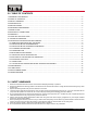
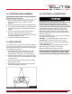
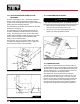
Refer to Figure 2.
Power Indicator Light (A) – lit whenever machine is
running.
Start Button (B) – press to start band saw.
Emergency Stop Button (C) – press to immediately stop
all machine functions.
Coolant Switch (D) – Turn arrow to “I” to turn on coolant
fl ow. Turn arrow to “O” to stop coolant fl ow.
Feed Rate Control (E) – this knob is used to set the
amount of downward force that is applied to the saw
blade. The feed rate is proportional to the opening of the
valve. When set to zero, the saw head is locked in the
raised position. Increasing the valve opening (counter-
clockwise adjustment) increases the feed rate; decreasing
the valve opening (clockwise adjustment) reduces the
feed rate.
10.0 AUXILIARY COOLANT HOSE
Your saw is equipped with an auxiliary coolant hose. This
can be used when a large amount of coolant needs to be
directed at the work piece.
11.0 PRIOR TO OPERATION
1. Check that blade tooth direction matches diagram on
blade guides.
2. Check to see that blade is properly seated on wheels
after applying correct tension (approximately 25,000
lbs.).
3. Set blade holder guides for approximately .003” to
.005” clearance between guides and blade.
4. Check for slight clearance between back up rollers
and back of blade.
5. Position blade guides as close to workpiece as pos-
sible.
6. Select proper speed and feed rate for material being
cut.
7. Material to be cut must be securely held in vise.
8. Check to see that coolant level is adequate and turn
on coolant pump if material to be cut requires it.
Machine should be fi lled with four gallons of the
proper coolant mixture. Follow the directions on the
product maker’s label and fi ll the coolant tank
through the chip tray area.
9. Do not start cut on a sharp edge.
10. Keep machine lubricated. See “Lubrication” section.
12.0 OPERATING CONTROLS AND
ADJUSTMENTS
12.1 REMOVING AND INSTALLING THE BLADE
When your machine was shipped, a blade was supplied
and assembled to the saw.
1. Disconnect the machine from the power source.
2. Raise the saw frame about 6” and close the feed rate
lever by turning it clockwise as far as it will go.
3. Open both wheel covers and clean the swarf out of
the machine.
4. Release blade tension by turning the blade tension
handwheel (C) Fig. 3 counterclockwise.
5. Remove the blade from both wheels and out of each
blade guide.
6. Make sure the teeth of the new blade are pointing in
the direction of travel. If necessary, turn the
blade inside out.
Fig. 2
A
C
B
E
D
If the bulb is out, lamp will not light, but machine
may still have power.