
Use and Care Manual

9
EHB-916V | EHB-1018V
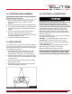
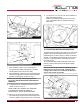
7. Place the blade in place on the wheels (A) and
through the upper blade guard (B) Fig. 3 is shown
with the wheel covers removed for clarity.
8. Work the blade (F) all the way up into the blade guide
roller bearings (D) with the back of the blade against
the back-up bearing (E), as shown in Fig. 4.
NOTE: If roller bearings need adjusting refer to
the section ADJUSTING BLADE GUIDE ROLLER
BEARINGS.
9. Put light tension on the blade and work it on both
wheels, as shown in Fig. 5.
MAKE SURE THAT THE BACK OF THE BLADE
IS AGAINST THE WHEEL FLANGES OF
BOTH WHEELS. THIS IS VERY IMPORTANT.
10. When you are sure the back of the blade is against
the wheel fl anges of both wheels and properly insert-
ed into the guides, fi nish putting tension on the blade.
Fig. 5
Fig. 3
C
A
A
B
Fig. 4
F
D
E
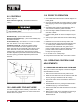
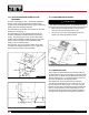
12.2 ADJUSTING BLADE GUIDE BRACKETS
The blade guides should be set as close to the vise jaw as
possible. The right blade guide bracket (A) Fig. 6, is not
adjustable and is set at the factory to clear the right hand
vise jaw. The left blade guide bracket (B) can be moved
to the left or right depending on the position of the left
hand vise jaw (C).
To move the left blade guide bracket (B), loosen hand
knob (D), position blade guide bracket (B) and tighten
hand knob (D).
Note: when operating 916/SA, the right blade guide
bracket (A) can be moved as well, especially when
cutting in 90° to make sure the bracket be moved as
close to the vise jaw as possible.
Fig. 6
A
B
C
D
11. Jog the power “on” and “off ” to be sure the blade is in
place and tracking properly.
If blade is not tracking properly refer to the section
12.11 “Adjust Blade Tension and Blade Tracking
Adjustment”.