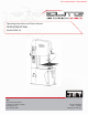
This .pdf document is bookmarked Operating Instructions and Parts Manual Vertical Band Saw Model EVBS-26 JET® 427 New Sanford Road LaVergne, Tennessee 37086 www.jettools.com Ph.: 855-336-4032 Part No.
1.0 WARRANTY AND SERVICE JET® warrants every product it sells against manufacturers’ defects. If one of our tools needs service or repair, please contact Technical Service by calling 1-855-336-4032, 8AM to 5PM CST, Monday through Friday. WARRANTY PERIOD The general warranty lasts for the time period specified in the literature included with your product or on the official JET branded website, jettools.com.
MORE INFORMATION JET® is constantly adding new products. For complete, up-to-date product information, check with your local distributor or visit the JET website, jettools.com. HOW STATE LAW APPLIES This warranty gives you specific legal rights, subject to applicable state law. LIMITATIONS ON THIS WARRANTY JET LIMITS ALL IMPLIED WARRANTIES TO THE PERIOD OF THE LIMITED WARRANTY FOR EACH PRODUCT.
2.0 TABLE OF CONTENTS 1.0 WARRANTY AND SERVICE .........................................................................................................................................2 2.0 TABLE OF CONTENTS .................................................................................................................................................4 3.0 SAFETY WARNINGS .........................................................................................................................................
3.0 SAFETY WARNINGS 1. Read and understand the entire owner’s manual before attempting assembly or operation. 2. Read and understand the warnings posted on the machine and in this manual. Failure to comply with all of these warnings may cause serious injury. 3. Replace the warning labels if they become obscured or removed. 4. This band saw is designed and intended for use by properly trained and experienced personnel only.
33. Adjust upper guide to clear workpiece. Hold workpiece firmly against table. 34. Direction of feed — feed work into a blade or cutter against the direction of rotation of the blade or cutter only. 35. Installation work and electrical wiring must be done by qualified electrician in accordance with all applicable codes and standards. 36. Do not remove jammed pieces until blade has stopped.
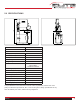
2120 658 700 1000 600 360 5.0 SPECIFICATIONS 1290 810 Model Number EVBS-26 Stock Number 891115 Capacities Height (max. in) Throat (max. in) Blade Speed 14” 26” Variable Low Range 50 High Range 5000 Motor Blade Length (in.) Blade Width (min.-max.) (in.) Table Size (LxW in.) Table Height (in.) Table Tilt (°) Overall Dimensions (LxWxH in.) 3HP 230/460V 8/4 A 1PH or 3PH CSA/CUS Certified 185-1/2 1/8-1 27-1/2x23-1/2 39-3/8 10 L, 45 R 51x32x83-1/2 Net Weight (lbs.) 1,433 Gross Weight (lbs.
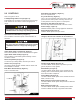
6.0 UNCRATING AND ASSEMBLY Note: Read and understand the entire manual before attempting setup or operation. 1. Finish uncrating the saw and inspect for damage. Should any have occurred, contact your local distributor. 2. Remove any preservatives with kerosene or diesel oil. Do not use gasoline, paint thinner, or any cellulosebased product, as these will damage painted surfaces. 3. Remove two socket head cap screws from left side of vertical column.
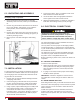
.0 CONTROLS Refer to Figures 2 and 3. Low/High Range Shift Lever (B, Figure 2) Pull toward front of machine to shift into low speed range. Push toward rear of machine to shift into high speed range. ! Move low/high range lever only while machine is STOPPED. Failure to comply may damage gearbox. Speed Selection Handwheel (V, Figure 2) Turn clockwise to increase speed, counterclockwise to decrease. Main Motor Stop Switch (I, Figure 3) Press to stop band saw.
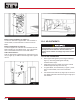
P O Q N R U Fig. 6 Fig. 4 Blade Tension Handwheel (S, Figure 5) Located on underside of upper frame. Turn clockwise to tension blade; counterclockwise to release tension on blade. Blade Tracking Knob (T, Figure 5) Located at upper rear of the saw. Turn clockwise to track blade toward front of the blade wheel. Turn counterclockwise to track blade toward rear of the blade wheel.
stabilize the new setting. 10.3 BLADE GUIDE ADJUSTMENT B ! Blade guides must be properly adjusted or damage may occur to blade and/or guides. A ! C Guard has been removed to show detail. Always operate saw with guard in place and properly adjusted. Failure to comply may cause serious injury. Fig. 7 10.2 BLADE TRACKING Blade tracking may be required periodically depending on the blade size and tension. The blade must be tensioned as outlined in section 10.1 Blade Tensioning.
10. Turn on saw and check blade tracking. Adjust tracking if necessary. H G I F Fig. 9 Fig. 10 10.4 TOP GUIDE ADJUSTMENT Always position top guide to within 1/8” of the top surface of workpiece. This minimizes exposure of operator’s hands to the saw blade. 10.5 CHANGING SAW BLADES 1. 2. 3. 4. 5. 6. Disconnect saw from power source. Move upper blade guide to its highest position and lock in place. Open both wheel doors. Turn tension adjustment knob counterclockwise to loosen tension on blade.
11.2 TOOTH SHAPE Note: When cutting thin materials, the rule for blade pitch is to have a minimum of two teeth engaging the material being cut at all times. Standard Tooth - generally used to cut ferrous metals, hard bronze, hard brass, and thin metals. Skip Tooth - have better chip clearance (larger gullet) and are used on softer, non-ferrous materials such as aluminum, copper, magnesium, and soft brass. Hook Tooth - provides a chip breaker and has less tendency to gum up in softer materials.
3. 4. Position blade so that cut is made at a place that allows for uniform spacing of teeth. See Figure 12. Bring handle down firmly to cut blade. GRIND HERE IMPORTANT: If a blade has been cut by using snips, the ends of the blade must be ground square before welding them together, as shown in Figure 14. If snips are used to cut blade, grind ends square as shown. Fig. 13 12.3 WELDING ! Fig. 11 The welder is designed for intermittent use.
6. Set pressure selector switch (counterclockwise rota tion) to the approximate setting required for the width of the blade being welded. Misaligned Weld ! Incomplete Weld Keep hands clear of weld area and clamp jaws during welding. 7. Press and hold weld button (Figure 14). When weld button is pushed, the left clamp moves to the right to apply pressure to the blade ends. Simultaneously, sparks will be emitted from the blade ends as they are being welded.
! If blade is thicker at the weld than at the rest of the blade, using the blade may damage the guides. The following are variations of the general procedure, based upon blade type: 12.4.1 CARBON STEEL BLADES 1. Press and jog the annealing switch button until weld is a “dull cherry” to “cherry red” color. 2. Allow blade to cool slowly by decreasing jogging frequency. 12.4.2 CARBON STEEL HARD BACK BLADES 1. Heat blade slowly until weld becomes a deep blue color. 2.
3. 4. 5. 6. Bad Grindings Fig. 18 13.2 SETTING BLADE SPEED 1. 12.6 SECONDARY ANNEALING Anneal the weld 2 to 3 times again after grinding. 12.7 WELDER CLEAN-UP It is important that the welder jaws be kept clean at all times. The jaws and inserts must be wiped or scraped clean after every weld. Doing this will ensure better welds by: 1. Holding proper alignment. 2. Preventing flash from becoming embedded in the blade. 3. Preventing shorts or poor electrical contact. 13.
14.0 MAINTENANCE ! Before doing maintenance on the machine, disconnect it from the electrical supply by pulling out the plug or switching off the main switch. Failure to comply may cause serious injury. Use a brush to loosen accumulated chips and debris. Use a shop vacuum to remove the debris. Make sure the chip brush on the lower band wheel is properly adjusted. If the power cord is worn, cut, or damaged in any way, have it replaced immediately.
15.0 TROUBLESHOOTING 15.1 OPERATING PROBLEMS Table 1 Trouble Saw blade is twisted. Cuts not straight. Blade slips off wheel(s). Blade quickly becomes dull. Blade warps. Band Saw is noisy, or vibrates too much. Blade teeth keep breaking. Blade becomes damaged easily. Probable Cause Remedy Blade has been improperly welded. Re-weld blade. See section 12.3 Blade not installed properly. Set guide inserts closer, and increase blade tension. Feeding workpiece too forcefully. Decrease feed rate.
15.2 MECHANICAL AND ELECTRICAL PROBLEMS Table 2 Trouble Machine will not start/restart or repeatedly trips circuit breaker or blows fuses. 20 Probable Cause Remedy No incoming power. Verify machine is connected to power source. Make sure START button is pushed in completely, and STOP button is disengaged. Cord damaged. Replace cord. Overload automatic reset has not reset.
Miswiring of the unit. Double check to confirm all electrical connections are correct. Refer to appropriate wiring diagrams to make any needed corrections. Switch failure. If switch is suspect, you have two options: Have a qualified electrician test the switch for function, or purchase a new start switch and establish if that was the problem on changeout. Extension cord too light or too long. Replace with adequate size and length cord. Low current. Contact a qualified electrician.
15.4 WELDER MECHANICAL PROBLEMS Table 4 Trouble Probable Cause Remedy Wire connection is poor; connecting point of welding switch is bad. Change switch, or grind the connecting port with a file. Transformer burned out. Change transformer, or rewire it. Blade has oil on it. Wipe off any oil. Blade ends have rust. Grind off rust. Welding switch is cutting off late. Screw welding switch connecting nut tighter. Welding press too weak. Rotate pressure selector knob accordingly.
16.
17.0 REPLACEMENT PARTS — EVBS 26 Replacement parts are listed on the following pages. To order parts or reach our service department, call 1-855-336-4032, Monday through Friday, 8:00 a.m. to 5:00 p.m. CST. Having the Model Number and Serial Number of your machine available when you call will allow us to serve you quickly and accurately. JET® 427 New Sanford Road LaVergne, Tennessee 37086 www.jettools.
BREAKDOWN ASSEMBLY — EVBS-26 EVBS-26 25
ASSEMBLY PARTS LIST — EVBS-26 26 Index No. 1 2 3 4 5 6 7 8 9 10 11 12 13 14 15 16 17 18 19 20 21 22 23 24 25 26 27 28 29 30 31 32 33 34 Part No.
Index No. 46 47 48 49 50 51 52 53 54 55 56 57 58 59 60 61 62 63 64 65 66 67 68 69 70 71 72 73 74 75 76 77 78 79 80 81 82 83 84 85 86 87 88 89 90 91 92 EVBS-26 Part No.
ASSEMBLY PARTS LIST (CONT’D) — EVBS-26 Index No. 93 94 95 96 97 99 100 101 102 103 104 105 106 107 108 109 110 111 112 113 114 115 116 117 118 119 120 121 122 123 124 125 126 127 128 129 130 131 132 133 134 135 136 137 138 28 Part No.
Index No. 139 140 141 142 143 144 145 146 147 148 149 150 151 152 153 154 155 156 157 158 159 160 161 162 163 164 166 167 168 169 170 171 Part No.
187 158 187 158 153 189 151 152 151 154 155 157 159 156 146 163 180 186 AT ION OF SA W 147 ER OP 182 172 184 181 178 ER LD WE 185 160 145 177 161 179 183 162 176 144 175 148 149 174 150 142 141 190 194 165 168 196 164 166 173 187 167 193 140 169 194 191 195 170 190 193 192 197 198 199 171 WELDER COMPONENT ASSEMBLY — EVBS-26 Vertical Band Saw
PARTS LIST WELDER COMPONENT — EVBS-26 Index No. 140 141 142 143 144 145 146 147 148 149 150 151 152 153 154 155 156 157 158 159 160 161 162 163 164 165 166 167 168 169 170 171 172 173 174 175 176 177 178 179 180 181 182 183 184 185 EVBS-26 Part No.
Index No. 186 187 188 189 190 191 192 193 194 195 196 197 198 199 200 32 Part No.
18.
2 3 TB1- TB1- L3 L2 L1 LIMIT OF EQUIPMENT 1 TB1- PE 3~ 60HZ QS L31 L21 L11 2.0MM 2 20A FU3 20A FU2 20A FU1 2 2 1 460V 2 1 1 TB2 7 230V TB2 6 FR 6~9A L22 L12 3 3 3 TB2 8 KM1 L32 TB2 9 4 4 4 34 TB2 10 1 2 5 5 5 U 6 6 6 U U U TB2 TB2 TB3 1 12 11 56 M1 3~ VW MAIN DRIVE MOTOR 3~ 2.25KW 60HZ W W V W V V TB3 2 1.
WIRING DIAGRAM 110V 31 26 TB1 - 4 31 110V 26 TB1 - 9 SQ1 22 0V 27 TB2 - 1 TB2 - 2 27 TB2 - 3 42 29 TB2 - 4 43 TB1 - 11 TB1 - 6 KM1 SB5 TB1 - 7 TB1 - 8 SA2 SA1 32 TB1 - 5 SQ2 FU8 1A FU7 2A SB4 TB1 - 12 SB3 34 30 22 M2 1~ GRINDER MOTOR 1~60HZ 110V 40W 22 31 EL HL FR WORKING LIGHT 0V SB1 WELD ON WHITE SA4 KEY SWITCH SB2 ANNEAL ON GREEN HL SB3 EMERGENCY STOP RED SB4 MAIN MOTOR OFF RED SB5 MAIN MOTOR ON GREEN SA1 GRINDER MOTOR ON SA2 WORK LAMP ON EVBS-
NOTES 36 Vertical Band Saw