
Use and Care Manual
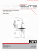
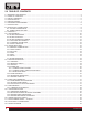
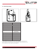
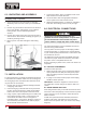
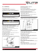
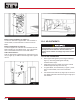
Table Of Contents
- Vertical Band Saw EVBS-26
- 1.0 WARRANTY AND SERVICE
- 2.0 TABLE OF CONTENTS
- 3.0 SAFETY WARNINGS
- 4.0 INTRODUCTION
- 5.0 SPECIFICATIONS
- 6.0 UNCRATING AND ASSEMBLY
- 7.0 INSTALLATION
- 8.0 ELECTRICAL CONNECTIONS
- 9.0 CONTROLS
- 10.0 ADJUSTMENTS
- 11.0 BLADE SELECTION
- 12.0 WELDER OPERATION
- 13.0 BAND SAW OPERATION
- 14.0 MAINTENANCE
- 15.0 TROUBLESHOOTING
- 16.0 SPEED AND PITCH CHART
- 17.0 REPLACEMENT PARTS —EVBS 26
- 18.0 ELECTRICAL CONNECTIONS — EVBS-26
- 19.0 WIRING DIAGRAM EVBS-26

9
EVBS-26
9.0 CONTROLS
Refer to Figures 2 and 3.
Low/High Range Shift Lever (B, Figure 2) -
Pull toward front of machine to shift into low speed range.
Push toward rear of machine to shift into high speed
range.
Speed Selection Handwheel (V, Figure 2) -
Turn clockwise to increase speed, counterclockwise to
decrease.
Upper Blade Guide Lock Knob (D, Figure 2) -
Turn counterclockwise to loosen and clockwise to tighten.
Upper Blade Guide Knob (E, Figure 2) -
Turn clockwise to raise blade guide assembly; counter-
clockwise to lower.
Work Lamp Switch (F, Figure 2) -
Located on top of lamp shade; turns lamp on and off.
Shear Lever (G, Figure 2) -
UP position allows insertion of blade end into shear. Pull
lever DOWN to cut blade.
Main Motor Start Switch (H, Figure 3) -
Press to start band saw.
!
Move low/high range lever only while machine is
STOPPED. Failure to comply may damage gearbox.
Grinder Toggle Switch (N, Figure 4) -
Located on blade welder panel. Flip switch up to start
grinder; fl ip down to stop grinder.
Weld Button (O, Figure 4) -
Located on blade welder panel. Press and hold to start
welding. Shuts off automatically when weld is done. Re-
lease when weld is completed.
Anneal Button (P, Figure 4) -
Located on blade welder panel. Press and hold to anneal
blade, release to stop.
Blade Clamp Pressure Knob (Q, Figure 4) -
Located on blade welder panel. Sets pressure for different
width blades.
Blade Clamps (R, Figure 4) -
Located on blade welder panel. DOWN position allows
insertion of blade into clamp. Up position locks blade.
Main Motor Stop Switch (I, Figure 3) -
Press to stop band saw.
Key Lock Switch (J, Figure 3) -
Turn to 12 o’clock position and remove key to lock out
power from the control panel. Insert key and turn to 3
o’clock position to turn on power to control panel.
Emergency Stop Switch (K, Figure 3) -
Press to stop all machine functions. Turn 90° to reset.
Power Lamp (L, Figure 3) -
Illuminated when power is being supplied to band saw.
Digital Readout (M, Figure 3) -
Indicates blade speed in feet per minute.
Note: After saw is fi rst started or the speed has been
changed, allow at least a minute for the readout to
Fig. 3
H
I
K
L
J
M
Fig. 2
B
E
D
G
F
V
!
Turn speed selection handwheel only while machine
is RUNNING. Failure to comply may damage gear-
box.