Operation and Safety Manual Original Instructions - Keep this manual with the machine at all times.
FOREWORD FOREWORD This manual is a very important tool! Keep it with the machine at all times. The purpose of this manual is to provide owners, users, operators, lessors, and lessees with the precautions and operating procedures essential for the safe and proper machine operation for its intended purpose. Due to continuous product improvements, JLG Industries, Inc. reserves the right to make specification changes without prior notification. Contact JLG Industries, Inc. for updated information.
FOREWORD SAFETY ALERT SYMBOLS AND SAFETY SIGNAL WORDS This is the Safety Alert Symbol. It is used to alert you to the potential personal injury hazards. Obey all safety messages that follow this symbol to avoid possible injury or death INDICATES AN IMMINENTLY HAZARDOUS SITUATION. IF NOT AVOIDED, WILL RESULT IN SERIOUS INJURY OR DEATH. THIS DECAL WILL HAVE A RED BACKGROUND. INDICATES A POTENTIALLY HAZARDOUS SITUATION. IF NOT AVOIDED, MAY RESULT IN SERIOUS INJURY OR DEATH.
FOREWORD For: THIS PRODUCT MUST COMPLY WITH ALL SAFETY RELATED BULLETINS. CONTACT JLG INDUSTRIES, INC. OR THE LOCAL AUTHORIZED JLG REPRESENTATIVE FOR INFORMATION REGARDING SAFETYRELATED BULLETINS WHICH MAY HAVE BEEN ISSUED FOR THIS PRODUCT. • Accident Reporting • Product Safety Publications • Current Owner Updates • Questions Regarding Product Safety JLG INDUSTRIES, INC. SENDS SAFETY RELATED BULLETINS TO THE OWNER OF RECORD OF THIS MACHINE. CONTACT JLG INDUSTRIES, INC.
FOREWORD REVISION LOG d Original Issue - April 15, 2009 Revised - May 2, 2012 – JLG Lift – 3121255
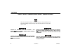
TABLE OF CONTENTS SECTION - PARAGRAPH, SUBJECT PAGE SECTION - PARAGRAPH, SUBJECT SECTION - 1 - SAFETY PRECAUTIONS 1.1 1.2 1.3 1.4 1.5 GENERAL . . . . . . . . . . . . . . . . . . . . . . . . . . . . . . . . .1-1 PRE-OPERATION . . . . . . . . . . . . . . . . . . . . . . . . . . .1-1 Operator Training and Knowledge . . . . . . . . . . . 1-1 Workplace Inspection . . . . . . . . . . . . . . . . . . . . . 1-2 Machine Inspection . . . . . . . . . . . . . . . . . . . . . . 1-2 OPERATION . . . . . . . . . . .
TABLE OF CONTENTS SECTION - PARAGRAPH, SUBJECT 4.3 4.4 4.5 4.6 4.7 4.8 4.9 4.10 4.11 4.12 4.13 4.14 ii PAGE CAPACITY SELECT (1100SJP ONLY). . . . . . . . . . . 4-4 ENGINE OPERATION . . . . . . . . . . . . . . . . . . . . . . . 4-7 Starting Procedure . . . . . . . . . . . . . . . . . . . . . . . 4-7 Shutdown Procedure . . . . . . . . . . . . . . . . . . . . . 4-7 TRAVELING (DRIVING) . . . . . . . . . . . . . . . . . . . . . . 4-8 Traveling Forward and Reverse. . . . . . . . . . . . 4-10 STEERING . . .
TABLE OF CONTENTS SECTION - PARAGRAPH, SUBJECT 6.3 6.4 PAGE SECTION - PARAGRAPH, SUBJECT OPERATOR MAINTENANCE . . . . . . . . . . . . . . . . .6-14 TIRES & WHEELS . . . . . . . . . . . . . . . . . . . . . . . . .6-21 Tire Inflation . . . . . . . . . . . . . . . . . . . . . . . . . . . 6-21 Tire Damage . . . . . . . . . . . . . . . . . . . . . . . . . . . 6-21 Tire Replacement . . . . . . . . . . . . . . . . . . . . . . . 6-22 Wheel Replacement . . . . . . . . . . . . . . . . . . . . .
TABLE OF CONTENTS SECTION - PARAGRAPH, SUBJECT PAGE LIST OF TABLES 1-1 1-2 2-1 4-1 4-2 4-3 4-4 6-1 6-2 6-3 6-4 6-5 6-6 6-7 6-8 6-9 6-10 iv Minimum Approach Distances (M.A.D.) . . . . . . . . . 1-5 Beaufort Scale (For Reference Only) . . . . . . . . . . 1-10 Inspection and Maintenance Table . . . . . . . . . . . . . 2-3 Decal Installation - 1100S - Prior to S/N 0300140836 . . . . . . . . . . . . . . . . . . . . . . . . . . 4-29 Decal Installation - 1100S - S/N 0300140836 to Present . . . . . . . . . . .
SECTION 1 - SAFETY PRECAUTIONS SECTION 1. SAFETY PRECAUTIONS 1.1 GENERAL 1.2 This section outlines the necessary precautions for proper and safe machine operation and maintenance. For proper machine use, it is mandatory that a daily routine is established based on the content of this manual. A maintenance program, using the information provided in this manual and the Service and Maintenance Manual, must also be established by a qualified person and followed to ensure the machine is safe to operate.
SECTION 1 - SAFETY PRECAUTIONS • Read, understand, and obey all DANGERS, WARNINGS, CAUTIONS, and operating instructions on the machine and in this manual. • Use the machine in a manner which is within the scope of its intended application set by JLG. • All operating personnel must be familiar with the emergency controls and emergency operation of the machine as specified in this manual.
SECTION 1 - SAFETY PRECAUTIONS 1.3 OPERATION • Supplies or tools which extend outside the platform are prohibited unless approved by JLG. General • When driving, always position boom over rear axle in line with the direction of travel. Remember, if boom is over the front axle, steer and drive functions will be reversed. • Do not use the machine for any purpose other than positioning personnel, their tools, and equipment.
SECTION 1 - SAFETY PRECAUTIONS • Before operating the machine, make sure all gates are closed and fastened in their proper position. • Use extreme caution when entering or leaving platform. Be sure that the boom is fully lowered. It may be necessary to telescope out to position the platform closer to the ground for entry/exit. Face the machine, maintain “three point contact” with the machine, using two hands and one foot or two feet and one hand during entry and exit.
SECTION 1 - SAFETY PRECAUTIONS Table 1-1. Minimum Approach Distances (M.A.D.) Voltage Range (Phase to Phase) 0 to 50 KV 10 (3) Over 50KV to 200 KV 15 (5) Over 200 KV to 350 KV 20 (6) Over 350 KV to 500 KV 25 (8) Over 500 KV to 750 KV 35 (11) Over 750 KV to 1000 KV 45 (14) NOTE: • Maintain distance from electrical lines, apparatus, or any energized (exposed or insulated) parts according to the Minimum Approach Distance (MAD) as shown in Table 11.
SECTION 1 - SAFETY PRECAUTIONS • The minimum approach distance may be reduced if insulating barriers are installed to prevent contact, and the barriers are rated for the voltage of the line being guarded. These barriers shall not be part of (or attached to) the machine. The minimum approach distance shall be reduced to a distance within the designed working dimensions of the insulating barrier.
SECTION 1 - SAFETY PRECAUTIONS • Do not elevate platform or drive with platform elevated while on a sloping, uneven, or soft surface. • If boom assembly or platform is in a position that one or more wheels are off the ground, all persons must be removed before attempting to stabilize the machine. Use cranes, forklift trucks, or other appropriate equipment to stabilize machine. • Before driving on floors, bridges, trucks, and other surfaces, check allowable capacity of the surfaces.
SECTION 1 - SAFETY PRECAUTIONS • Use the boom functions, not the drive function, to position the platform close to obstacles. • Always post a lookout when driving in areas where vision is obstructed. • Keep non-operating personnel at least 6 ft. (1.8m) away from machine during all driving and swing operations. • Limit travel speed according to conditions of ground surface, congestion, visibility, slope, location of personnel, and other factors which may cause collision or injury to personnel.
SECTION 1 - SAFETY PRECAUTIONS 1.5 ADDITIONAL HAZARDS / SAFETY • Do not refuel the machine with the engine running. • Battery fluid is highly corrosive. Avoid contact with skin and clothing at all times. • Do not use machine as a ground for welding. • When performing welding or metal cutting operations, precautions must be taken to protect the chassis from direct exposure to weld and metal cutting spatter. 3121255 – JLG Lift – • Charge batteries only in a well ventilated area.
SECTION 1 - SAFETY PRECAUTIONS DO NOT OPERATE THE MACHINE WHEN WIND CONDITIONS EXCEED 28 MPH (12.5 M/S). Table 1-2. Beaufort Scale (For Reference Only) 1-10 Wind Speed Beaufort Number mph m/s 0 0 0-0.2 1 1-3 0.3-1.5 Light air Wind motion visible in smoke 2 4-7 1.6-3.3 Light breeze Wind felt on exposed skin. Leaves rustle 3 8-12 3.4-5.4 Gentle breeze Leaves and smaller twigs in constant motion 4 13-18 5.5-7.9 Moderate breeze Dust and loose paper raised.
SECTION 2 - USER RESPONSIBILITIES, MACHINE PREPARATION, AND INSPECTION SECTION 2. USER RESPONSIBILITIES, MACHINE PREPARATION, AND INSPECTION 2.1 PERSONNEL TRAINING 6. The safest means to operate the machine where overhead obstructions, other moving equipment, and obstacles, depressions, holes, drop-offs. The aerial platform is a personnel handling device; so it is necessary that it be operated and maintained only by trained personnel.
SECTION 2 - USER RESPONSIBILITIES, MACHINE PREPARATION, AND INSPECTION 2.2 PREPARATION, INSPECTION, AND MAINTENANCE The following table covers the periodic machine inspections and maintenance required by JLG Industries, Inc. Consult local regulations for further requirements for aerial work platforms.
SECTION 2 - USER RESPONSIBILITIES, MACHINE PREPARATION, AND INSPECTION Table 2-1. Inspection and Maintenance Table Type Primary Responsibility Frequency Service Qualification Reference Pre-Start Inspection Before using each day; or whenever there’s an Operator change. User or Operator User or Operator Operator and Safety Manual Pre-Delivery Inspection (See Note) Before each sale, lease, or rental delivery.
SECTION 2 - USER RESPONSIBILITIES, MACHINE PREPARATION, AND INSPECTION Pre-Start Inspection The Pre-Start Inspection should include each of the following: 1. Cleanliness – Check all surfaces for leakage (oil, fuel, or battery fluid) or foreign objects. Report any leakage to the proper maintenance personnel. 2. Structure - Inspect the machine structure for dents, damage, weld or parent metal cracks or other discrepancies. 4.
SECTION 2 - USER RESPONSIBILITIES, MACHINE PREPARATION, AND INSPECTION 11. Function Check – Once the “Walk-Around” Inspection is complete, perform a functional check of all systems in an area free of overhead and ground level obstructions. Refer to Section 4 for more specific operating instructions. Function Check 12. Boom Control System Check - Perform a check of the boom control system as specified in this section.
SECTION 2 - USER RESPONSIBILITIES, MACHINE PREPARATION, AND INSPECTION Boom Control System Check Procedure 4. With the platform in the (stowed) position: a. Drive the machine on a grade, not to exceed the rated gradeability, and stop to ensure the brakes hold; Perform the following check with no load (personnel or material) in the platform from the ground control station with the machine on a firm, level surface. b. Check that the tilt indicator is illuminated to ensure proper operation. 1.
3121255 – JLG Lift – 1. 2. 3. 4. 5. 6. 7. 4 9 1 3 10 8. 9. 10. 11. 12. 13. 2 Fly Boom Section Boom Assembly Power Track Jib Platform Platform Console 10 11 Figure 2-1.
SECTION 2 - USER RESPONSIBILITIES, MACHINE PREPARATION, AND INSPECTION 7 7 6 10 14 10 6 12 12 8 2 3 5 10 11 4 16 13 10 13 13 10 15 2 9 10 12 8 1 12 7 6 7 6 Figure 2-2.
SECTION 2 - USER RESPONSIBILITIES, MACHINE PREPARATION, AND INSPECTION General 3. Console Cover - Detent functions properly, smooth operation. Begin the "Walk-Around Inspection" at Item 1, as noted on the diagram. Continue checking each item in sequence for the conditions listed in the following checklist. TO AVOID POSSIBLE INJURY, BE SURE MACHINE POWER IS OFF. DO NOT OPERATE MACHINE UNTIL ALL MALFUNCTIONS HAVE BEEN CORRECTED.
SECTION 2 - USER RESPONSIBILITIES, MACHINE PREPARATION, AND INSPECTION 12. Steering Spindles and Sensors - See Inspection Note. 15. Platform Rotator - See Inspection Note. 16. Jib Rotator (1100SJP Only) - See Inspection Note. 13. Horizontal and Capacity Limit Switches - Switches operate properly. 14. Main Hydraulic Pump - See Inspection Note. Figure 2-4.
SECTION 2 - USER RESPONSIBILITIES, MACHINE PREPARATION, AND INSPECTION 2.3 OSCILLATING AXLE LOCKOUT TEST (IF EQUIPPED - 1100SJP ONLY) 5. With boom in this position, place Drive control lever to Reverse and carefully drive machine off of block and ramp. The front axles will oscillate when the boom is in the transport position (i.e. when the boom is less than 15° above horizontal and not extended beyond 24" [60.9 cm]) and drive is selected.
SECTION 2 - USER RESPONSIBILITIES, MACHINE PREPARATION, AND INSPECTION NOTES: 2-12 – JLG Lift – 3121255
SECTION 3 - MACHINE CONTROLS AND INDICATORS SECTION 3. MACHINE CONTROLS AND INDICATORS 3.1 GENERAL NOTE: THE MANUFACTURER HAS NO DIRECT CONTROL OVER MACHINE APPLICATION AND OPERATION. THE USER AND OPERATOR ARE RESPONSIBLE FOR CONFORMING WITH GOOD SAFETY PRACTICES. Indicates a potentially hazardous situation, which if not corrected, could result in serious injury or death. This indicator will be red. This section provides the necessary information needed to understand control functions. 3.
SECTION 3 - MACHINE CONTROLS AND INDICATORS Ground Control Station NOTE: 4. Swing Control Provides 360 degrees continuous turntable rotation. The Function Enable switch must be held down in order to operate boom and platform functions. 5. Lift Control Provides raising and lowering of the boom. NOTE: The Boom Control system will only allow the boom to operate in Automatic mode from the Ground Control Station. (See Figure 3-1., Ground Control Station - 1100S and Figure 3-2.
SECTION 3 - MACHINE CONTROLS AND INDICATORS 12 1 2 11 3 10 9 1. Indicator Panel 2. Boom Control System Test Button 3. Telescope 4. Swing 5. Lift 6. Platform/Ground Select Switch 7. Hourmeter 8. Emergency Stop Switch 9. Engine Start/Auxiliary Power/Function Enable 10. Articulating Jib 11. Platform Leveling Override 12. Platform Rotate 8 7 1001109653_ A 4 5 6 Figure 3-1.
SECTION 3 - MACHINE CONTROLS AND INDICATORS 1 13 12 2 11 3 10 9 1. Indicator Panel 2. Boom Control System Test Button 3. Telescope 4. Swing 5. Lift 6. Platform/Ground Select Switch 7. Hourmeter 8. Emergency Stop Switch 9. Engine Start/Auxiliary Power/Function Enable 10. Articulating Jib 11. Platform Leveling Override 12. Platform Rotate 13. Jib Swing 8 7 1706911 A 4 5 6 Figure 3-2.
SECTION 3 - MACHINE CONTROLS AND INDICATORS NOTE: When Emergency Stop switch is in the “ON” position and engine is not running, an alarm will sound, indicating Ignition is “ON”. NOTE: Auxiliary power only works if there is no engine oil pressure, and is disabled if engine is running. Functions will operate at a slower than normal rate because of the lesser flow of hydraulic fluid delivered.
SECTION 3 - MACHINE CONTROLS AND INDICATORS Ground Control Indicator Panel 10. Articulating Jib This switch provides raising and lowering of the jib. (See Figure 3-3., Ground Control Indicator Panel - 1100S and Figure 3-4., Ground Control Indicator Panel - 1100SJP) ONLY USE THE PLATFORM LEVELING OVERRIDE FUNCTION FOR SLIGHT LEVELING OF THE PLATFORM. INCORRECT USE COULD CAUSE THE LOAD/OCCUPANT TO SHIFT OR FALL. FAILURE TO DO SO COULD RESULT IN DEATH OR SERIOUS INJURY. 1.
SECTION 3 - MACHINE CONTROLS AND INDICATORS 1 2 3 9 1. 2. 3. 4. 5. 4 5 6 7 1 8 3 9 Battery Charging 6. Axles Set Low Engine Oil Pressure 7. Platform Capacity 8. Boom Control System Warning High Engine Coolant Temp. High Engine Oil Temp. 9. Boom Control System Test Glow Plug Indicator Figure 3-3. Ground Control Indicator Panel - 1100S 3121255 2 1. 2. 3. 4. 5. – JLG Lift – 4 5 6 7 8 Battery Charging 6. Axles Set Low Engine Oil Pressure 7. Platform Capacity 8.
SECTION 3 - MACHINE CONTROLS AND INDICATORS 4. Engine Oil Temperature Indicator 8. Boom Control System Warning Indicator Indicates the temperature of the engine oil, which also serves as engine coolant, is abnormally high and service is required. Indicates the platform is outside the operating area and operation of certain boom functions may be disabled (i.e. lift, telescope). Attempts to use the disabled functions cause the indicator to flash and an alarm to sound.
SECTION 3 - MACHINE CONTROLS AND INDICATORS Platform Station 2. Start/Auxiliary Power (See Figure 3-5., Platform Control Console - 1100S and Figure 3-6., Platform Control Console - 1100SJP) TO AVOID SERIOUS INJURY, DO NOT OPERATE MACHINE IF ANY CONTROL LEVERS OR TOGGLE SWITCHES CONTROLLING PLATFORM MOVEMENT DO NOT RETURN TO THE OFF OR NEUTRAL POSITION WHEN RELEASED. 1. Emergency Stop Switch A two-position red mushroom shaped switch furnishes power to PLATFORM Controls when pulled out (on).
SECTION 3 - MACHINE CONTROLS AND INDICATORS 19 11 20 21 22 1 2 4 1706741A 17 1001109649_A 1001109650_A 1705170 A 1001113691 16 1. 2. 3. 4. 5. 6. Emergency Stop Engine Start / Aux Power Not Used Drive Orientation Override Drive/Steer Main Boom Telescope 15 7. 8. 9. 10. 11. 12. 13 Lights Jib Lift Soft Touch Override Not Used Axle Extend/Retract Soft Touch Indicator 9 12 13. 14. 15. 16. 17. 18.
SECTION 3 - MACHINE CONTROLS AND INDICATORS 18 19 11 20 21 22 1 2 3 4 1706741A 17 1705744 A 1705973 A 1705745 B 1705170 A 1705171 A 16 1. 2. 3. 4. 5. Power/Emergency Stop Engine Start / Aux Power Capacity Select Drive Orientation Override Drive/Steer 3121255 15 14 13 10 8 7 6 6. Telescope 11. Axle Extend/Retract 15. Function Speed Control 7. Lights 12. Not Used 16. Main Lift / Swing 8. Jib Lift 13. Platform Rotate 17. Drive Speed / Torque Select 9. Not Used 14.
SECTION 3 - MACHINE CONTROLS AND INDICATORS 4. Drive Orientation Override 6. Main Telescope When the boom is swung over the rear tires or further in either direction, the Drive Orientation indicator will illuminate when the drive function is selected. Push and release the switch, and within 3 seconds move the Drive/Steer control to activate drive or steer. Before driving, locate the black/white orientation arrows on both the chassis and the platform controls.
SECTION 3 - MACHINE CONTROLS AND INDICATORS NOTE: The Jib Swing function is not operable when the Capacity Select control is in the 1000 lb. (450 kg) position. 13. Platform Rotate This switch allows the operator to rotate the basket to the left or right. 10. Jib Swing (1100SJP Only) This switch allows the operator to rotate the jib to the left or right. 11. Axle Extend/Retract This switch allows the operator to extend or retract the axles.
SECTION 3 - MACHINE CONTROLS AND INDICATORS NOTE: To operate the Main Lift/Swing Joystick, pull up on the locking ring below the handle. NOTE: The MAIN LIFT/SWING control lever is spring-loaded and will automatically return to neutral (OFF) position when released. When boom is positioned above transport position or telescoped out high function speeds are automatically cut out and the machine continues to operate at a lower speed.
SECTION 3 - MACHINE CONTROLS AND INDICATORS 18. Steer Select (1100SJP Only) When equipped with four wheel steering, the action of the steering system is operator selectable. The center switch position gives conventional front wheel steering with the rear wheels unaffected. This is for normal driving at maximum speeds. The forward position is for “crab” steering. When in this mode both front and rear axles steer in the same direction, which allows the chassis to move sideways as it goes forward.
SECTION 3 - MACHINE CONTROLS AND INDICATORS 22. Boom Control Select Manual Mode: Automatic Mode: When the Boom Control is positioned to Automatic, lift and telescope movements are coordinated by the JLG control system and the automatic platform leveling feature is active during lift, telescope, swing, and drive movements. NOTE: 3-16 • While operating lift up, the boom may also telescope out. • While operating lift down, the boom may also telescope in.
SECTION 3 - MACHINE CONTROLS AND INDICATORS Platform Control Indicator Panel 3. Platform Capacity Indicator Indicates the maximum platform capacity for the platform. (See Figure 3-7., Platform Control Indicator Panel - 1100S or Figure 3-8., Platform Control Indicator Panel - 1100SJP) 1. Level System Fault Indicator On 1100SJP models, one of the capacity lights should be on at all times.
SECTION 3 - MACHINE CONTROLS AND INDICATORS 1 3 13 12 1. 2. 3. 4. 5. 3-18 11 4 5 6 10 9 8 7 Level System 6. Enable 10. Cable Service Not Used 7. Fuel Level 11. Drive Orientation Platform Capacity 8. Creep Speed 12. Axles Set Tilt Alarm Warning 9. System Distress 13. Boom Control System Warning Glow Plug Figure 3-7.
SECTION 3 - MACHINE CONTROLS AND INDICATORS 3 1. 2. 3. 4. 5. 3121255 Level System 6. Enable 10. Cable Service AC Generator 7. Fuel Level 11. Drive Orientation Platform Capacity 8. Creep Speed 12. Axles Set Tilt Alarm Warning 9. System Distress 13. Boom Control System Warning Glow Plug Figure 3-8.
SECTION 3 - MACHINE CONTROLS AND INDICATORS 5. Glow Plug Indicator Indicates the glow plugs are operating. After turning on ignition, wait until light goes out before cranking engine. 6. Footswitch/Enable Indicator To operate any function, the footswitch must be depressed and the function selected within seven seconds. The enable indicator shows that the controls are enabled.
SECTION 3 - MACHINE CONTROLS AND INDICATORS 9. System Distress Indicator 12. Axles Set Indicator The light indicates that the JLG Control System has detected a malfunction and a Diagnostic Trouble Code has been set in the system memory. Refer to the Service Manual for instructions concerning the trouble codes and trouble code retrieval. The malfunction indicator light will illuminate for 2-3 seconds when the key is positioned to the on position to act as a self test. 10.
SECTION 3 - MACHINE CONTROLS AND INDICATORS NOTES: 3-22 – JLG Lift – 3121255
SECTION 4 - MACHINE OPERATION SECTION 4. MACHINE OPERATION 4.1 DESCRIPTION 4.2 This machine is a self-propelled hydraulic lift equipped with a work platform on the end of an elevating and rotating boom. Vibrations emitted by these machines are not hazardous to an operator in the work platform. Capacities The primary operator control station is in the platform. From this control station, the operator can drive and steer the machine in both forward and reverse directions.
SECTION 4 - MACHINE OPERATION Controlled Arc platform through a predetermined arc, equivalent to the percentage of extension. (i.e. If you start at 70% boom extension, you will end up at approximately 70% boom extension no matter where you stop in the arc). This means that when lifting down, telescope in will function automatically, or when lifting up, telescope out will function automatically.
SECTION 4 - MACHINE OPERATION Envelope Tracking stop when the end of the envelope is reached and the operator must activate lift and/or telescope in the proper direction to bring the boom back into the envelope. ENVELOPE The Boom Control system will only allow the boom to operate in Automatic mode from the Ground Control Station.
SECTION 4 - MACHINE OPERATION Stability 4.3 Machine stability is based on two (2) conditions which are called FORWARD and BACKWARD stability. The machine’s position of least FORWARD stability is shown in (See Figure 4-1.), and its position of least BACKWARD stability is shown in (See Figure 4-2.) TO AVOID FORWARD OR BACKWARD TIPPING, DO NOT OVERLOAD MACHINE OR OPERATE THE MACHINE ON AN OUT-OF-LEVEL SURFACE.
SECTION 4 - MACHINE OPERATION Figure 4-1.
SECTION 4 - MACHINE OPERATION . . ROTATE PLATFORM 90 DEGREES Figure 4-2. Position of Least Backward Stability - 1100S 4-6 Figure 4-3.
SECTION 4 - MACHINE OPERATION 4.4 ENGINE OPERATION NOTE: 3. Turn Platform/Ground Select switch to PLATFORM. 4. From Platform, pull EMERGENCY STOP switch out, then push the ENGINE START switch until engine starts. Initial starting should always be performed from the Ground Control station. NOTE: Starting Procedure IF ENGINE FAILS TO START PROMPTLY, DO NOT CRANK FOR AN EXTENDED TIME. SHOULD ENGINE FAIL TO START AGAIN, ALLOW STARTER TO “COOL OFF” FOR 2-3 MINUTES.
SECTION 4 - MACHINE OPERATION 4.5 TRAVELING (DRIVING) See Figure 4-4., Grade and Side Slopes NOTE: When the boom is raised approximately 15 degrees above horizontal or telescoped out 24 inches (60.9 cm), the high drive function will automatically be in low drive. NOTE: Refer to the Operating Specifications table for Gradeability and Sideslope ratings. BEFORE DRIVING, LOCATE THE BLACK/WHITE ORIENTATION ARROWS ON BOTH THE CHASSIS AND THE PLATFORM CONTROLS.
SECTION 4 - MACHINE OPERATION GRAD E LEVEL OPE SIDESL Figure 4-4.
SECTION 4 - MACHINE OPERATION Traveling Forward and Reverse 4.6 1. At Platform Controls, pull out Emergency Stop switch, start engine, and activate footswitch. STEERING Position thumb switch on Drive/Steer controller to RIGHT for steering right, or to LEFT for steering left. 2. Position Drive controller to FORWARD or REVERSE as desired. 4.7 This machine is equipped with a Drive Orientation Indicator.
SECTION 4 - MACHINE OPERATION 4.8 PLATFORM Platform Rotation Platform Level Adjustment NOTE: When the Boom Control Select Switch is in the Manual mode, Platform leveling only functions during Main Lift operation. When the Boom Control Select Switch is in the Automatic mode, Platform Leveling is active during all functions except during telescope operation. Also, when in the Manual mode, the Controlled Angle system is not active.
SECTION 4 - MACHINE OPERATION 4.9 BOOM Swinging the Boom To swing boom, use Swing control to select Right or Left direction. DO NOT SWING OR RAISE BOOM ABOVE HORIZONTAL WHEN MACHINE IS OUT OF LEVEL. DO NOT DEPEND ON TILT ALARM AS A LEVEL INDICATOR FOR THE CHASSIS. WHEN SWINGING THE BOOM MAKE SURE THERE IS AMPLE ROOM FOR THE BOOM TO CLEAR SURROUNDING WALLS, PARTITIONS AND EQUIPMENT. TO AVOID TIP OVER, LOWER PLATFORM TO GROUND LEVEL. THEN DRIVE MACHINE TO A LEVEL SURFACE BEFORE RAISING BOOM.
SECTION 4 - MACHINE OPERATION Swinging the Jib (1100SJP Only) NOTE: 4.11 EMERGENCY TOWING For 1000 lb. (450 kg) mode operation, the jib must be centered and the Jib Swing function is not operable. If the jib is out of the centered position when in this mode, the indicator will flash and the alarm sound until the jib is centered again. The jib swing function will allow the operator to center the jib again. To swing the jib, use the Jib Swing control to select Right or Left direction.
SECTION 4 - MACHINE OPERATION 4.12 SHUT DOWN AND PARK 2. Disconnect drive hubs by inverting disconnect cap. To shut down and park the machine, the procedures are as follows: 1. Drive machine to a reasonably well protected area. 2. Ensure boom is lowered over rear drive axle. 3. Push in the Emergency Stop at Platform Controls. 4. Push in the Emergency Stop at Ground Controls. Position Platform/Ground Select switch to center OFF. 5.
SECTION 4 - MACHINE OPERATION 4.13 LIFTING AND TIE DOWN Tie Down See Figure 4-6. and Figure 4-7. Lifting WHEN TRANSPORTING THE MACHINE, THE BOOM MUST BE FULLY LOWERED INTO THE BOOM REST. 1. Refer to the serial number plate, the General Specifications & Operator Maintenance section of this manual, or weigh the individual unit to find out the Gross Vehicle Weight. NOTE: 2. Place the boom in the stowed position with the turntable locked. 3. Remove all loose items from the machine. 1.
SECTION 4 - MACHINE OPERATION 4.14 STOWING THE JIB FOR TRANSPORT (1100SJP ONLY) Automatic platform leveling is disabled when stowing the jib. 1. Place the boom in the stowed position with the axles retracted. 3. Push and hold the Jib Stow override control switch and jib swing switch until the jib and platform are in the stowed position under the boom. 2. Hold the Jib Swing control switch to the right until the platform will no longer swing. 4. Rotate the platform completely to the right.
SECTION 4 - MACHINE OPERATION This page left blank intentionally.
SECTION 4 - MACHINE OPERATION R 7’10”/2.39 m 1001110901_A 10’9”/3.28 m 18’7”/5.66 m Figure 4-6.
SECTION 4 - MACHINE OPERATION R 11’2”/3.4 m 34’1”/10.38 m Figure 4-7.
SECTION 4 - MACHINE OPERATION Figure 4-8.
SECTION 4 - MACHINE OPERATION R 27’9"/8.46 m (1350SJP) 11’2”/3.40 m 23’9”/7.24 m 38’11”/11.86 m (1350SJP) 34’11”/10.64 m 1705096 C Figure 4-9.
SECTION 4 - MACHINE OPERATION 48 18 39 23 37 8 2 65 41 27 39 42 57 Figure 4-10.
SECTION 4 - MACHINE OPERATION 59 31 33 9 9 24 20 19 44 28 26 59 15 5 43 45 15 19 16 59 28 52 58 56 54 58 52 58 55 53 56 22 Figure 4-11.
SECTION 4 - MACHINE OPERATION 31 33 19 9 9 19 28 44 22 45 43 24 Figure 4-12.
SECTION 4 - MACHINE OPERATION 1001112830 KOR 1001112831 CHI 1001112727 KOR 1001112145 CHI 1705503 KOR 1705507 CHI 1001112820-A 1001112821-A Figure 4-13.
SECTION 4 - MACHINE OPERATION 48 34 23 18 39 32 41 65 39 30 8 2 37 Figure 4-14.
SECTION 4 - MACHINE OPERATION 37 35 36 37 34 10 Figure 4-15.
SECTION 4 - MACHINE OPERATION 7 13 21 29 25 23 29 26 23 16 22 49 www.jlg.com 22 23 45 40 2 18 7 8 8 Figure 4-16.
SECTION 4 - MACHINE OPERATION Table 4-1.
SECTION 4 - MACHINE OPERATION Table 4-1.
SECTION 4 - MACHINE OPERATION Table 4-1.
SECTION 4 - MACHINE OPERATION Table 4-1.
SECTION 4 - MACHINE OPERATION Table 4-2.
SECTION 4 - MACHINE OPERATION Table 4-2.
SECTION 4 - MACHINE OPERATION Table 4-2.
SECTION 4 - MACHINE OPERATION Table 4-2.
SECTION 4 - MACHINE OPERATION Table 4-3.
SECTION 4 - MACHINE OPERATION Table 4-3.
SECTION 4 - MACHINE OPERATION Table 4-3.
SECTION 4 - MACHINE OPERATION Table 4-3.
SECTION 4 - MACHINE OPERATION Table 4-4.
SECTION 4 - MACHINE OPERATION Table 4-4.
SECTION 4 - MACHINE OPERATION Table 4-4.
SECTION 4 - MACHINE OPERATION Table 4-4.
SECTION 5 - EMERGENCY PROCEDURES SECTION 5. EMERGENCY PROCEDURES 5.1 GENERAL This section explains the steps to be taken in case of an emergency situation while operating. 5.2 INCIDENT NOTIFICATION JLG Industries, Inc. must be notified immediately of any incident involving a JLG product. Even if no injury or property damage is evident, the factory should be contacted by telephone and provided with all necessary details.
SECTION 5 - EMERGENCY PROCEDURES Platform or Boom Caught Overhead 5.4 If the platform or boom becomes jammed or snagged in overhead structures or equipment, rescue platform occupants prior to freeing the machine. 5-2 EMERGENCY TOWING PROCEDURES Towing this machine is prohibited, unless properly equipped. However, provisions for moving the machine have been incorporated. For specific procedures, refer to Section 4.11, EMERGENCY TOWING.
SECTION 6 - GENERAL SPECIFICATIONS & OPERATOR MAINTENANCE SECTION 6. GENERAL SPECIFICATIONS & OPERATOR MAINTENANCE 6.1 INTRODUCTION 6.2 This section of the manual provides additional necessary information to the operator for proper operation and maintenance of this machine.
SECTION 6 - GENERAL SPECIFICATIONS & OPERATOR MAINTENANCE Dimensional Data Table 6-2. Operating Specifications - S/N 0300140836 to Present Table 6-3. Dimensional Data Maximum Work Load (Capacity) - 1100SJP Unrestricted Restricted 500 lb (230 kg) 1000 lb. (450 kg) Maximum Work Load (Capacity) - 1100SJP ANSI Unrestricted Restricted 500 lb (227 kg) 1000 lb. (454 kg) Overall Width Axles Retracted Axles Extended 8ft. 2in. (2.49 m) 12ft. 6in. (3.81 m) Stowed Height 10ft. (3.
SECTION 6 - GENERAL SPECIFICATIONS & OPERATOR MAINTENANCE Chassis Table 6-4. Chassis Specifications Table 6-4. Chassis Specifications Maximum Travel Grade With boom in stowed position (Gradeability) (1100SJP) 45% Maximum Travel Grade With boom in stowed position (Gradeability) (1100S) 30% Maximum Travel Grade With boom in stowed position (Side Slope) 5° Turning Radius - 1100SJP (Axles Retracted) Outside Inside 22 ft. 6 in. (6.8 m) 14 ft. 5 in. (4.
SECTION 6 - GENERAL SPECIFICATIONS & OPERATOR MAINTENANCE Capacities Engine Data Table 6-7. Deutz TD2011L4 Specifications Table 6-5. Capacities Hydraulic Tank 55 gallons (208 liters) Type Fuel Tank 53 gallons (200 liters) Number of Cylinders 4 66 gallons (250 liters) Bore 3.7 in. (94 mm) Hydraulic System Stroke 4.4 in. (112 mm) Total Displacement 190 cu. in. (3108 cm³) Compression Ratio 17.
SECTION 6 - GENERAL SPECIFICATIONS & OPERATOR MAINTENANCE Engine Data - Caterpillar Hydraulic Oil Table 6-8. Caterpillar 3.4T Table 6-9. Hydraulic Oil Specifications Type Liquid Cooled, Antifreeze Number of Cylinders 4 Bore 3.7 in. (94 mm) Stroke 4.7 in. (120 mm) Total Displacement 201 cu. in. (3294 cm³) Compression Ratio 19.5:1 Firing Order 1-3-4-2 Output 73.7hp (55 kW) Oil Capacity 10.5 Quarts (10 L) Average Fuel Consumption 1.36 gph (5.
SECTION 6 - GENERAL SPECIFICATIONS & OPERATOR MAINTENANCE Table 6-10. Mobilfluid 424 Specs Table 6-11. Mobil DTE 13M Specs SAE Grade 10W30 ISO Viscosity Grade #32 Gravity, API 29.0 Specific Gravity 0.877 Density, Lb/Gal. 60°F 7.35 Pour Point, Max -40°F (-40°C) Pour Point, Max -46°F (-43°C) Flash Point, Min. Flash Point, Min. 442°F (228°C) at 40° C 33cSt 2700 at 100° C 6.
SECTION 6 - GENERAL SPECIFICATIONS & OPERATOR MAINTENANCE Table 6-12. UCon Hydrolube HP-5046 Table 6-13. Mobil EAL H 46 Specs Type Synthetic Biodegradable Type Synthetic Biodegradable Specific Gravity 1.082 ISO Viscosity Grade 46 Pour Point, Max -58°F (-50°C) Specific Gravity .910 pH 9.1 Pour Point -44°F (-42°C) Flash Point 500°F (260°C) at 0° C (32° F) 340 cSt (1600SUS) Operating Temp.
SECTION 6 - GENERAL SPECIFICATIONS & OPERATOR MAINTENANCE Table 6-14. Exxon Univis HVI 26 Specs Specific Gravity 32.1 Pour Point -76°F (-60°C) Flash Point 217°F (103°C) Viscosity NOTE: 6-8 Major Component Weights Table 6-15. Component Weights Component Tire & Wheel Drive Hub & Motor Pounds Kilograms 867 393 275.5 123 290 132 at 40° C 25.8 cSt Swing Drive at 100° C 9.
SECTION 6 - GENERAL SPECIFICATIONS & OPERATOR MAINTENANCE AMBIENT AIR TEMPERATURE 120° F(49° C) NO OPERATION ABOVE THIS AMBIENT TEMPERATURE 110° F(43° C) 100° F(38° C) 90° F(32° C) ENGINE SPECIFICATIONS SUMMER GRADE FUEL 80° F(27° C) 70° F(21° C) 60° F(16° C) 50° F(10° C) 40° F(4° C) 30° F(-1° C) ENGINE WILL START AND OPERATE UNAIDED AT THIS TEMPERATURE WITH THE RECOMMENDED FLUIDS AND A FULLY CHARGED BATTERY.
SECTION 6 - GENERAL SPECIFICATIONS & OPERATOR MAINTENANCE EXTENDED DRIVING WITH HYDRAULIC OIL TANK TEMPERATURES OF 180° F (82°C) OR ABOVE. 180° F (82° C) (HYD. OIL TANK TEMP.
SECTION 6 - GENERAL SPECIFICATIONS & OPERATOR MAINTENANCE AMBIENT AIR TEMPERATURE 120 F(49 C) NO OPERATION ABOVE THIS AMBIENT TEMPERATURE 110 F(43 C) 100 F(38 C) 90 F(32 C) 80 F(27 C) 70 F(21 C) ENGINE SPECIFICATIONS 60 F(16 C) 50 F(10 C) 40 F(4 C) 30 F(-1 C) ENGINE WILL START AND OPERATE UNAIDED AT THIS TEMPERATURE WITH THE RECOMMENDED FLUIDS AND A FULLY CHARGED BATTERY.
SECTION 6 - GENERAL SPECIFICATIONS & OPERATOR MAINTENANCE EXTENDED DRIVING WITH HYDRAULIC OIL TANK TEMPERATURES OF 180° F (82°C) OR ABOVE. 180° F (82° C) (HYD. OIL TANK TEMP.) IF EITHER OR BOTH CONDITIONS EXIST JLG HIGHLY RECOMMENDS THE ADDITION OF A HYDRAULIC OIL COOLER (CONSULT JLG SERVICE AMBIENT AIR TEMPERATURE 120° F (49° C) NO OPERATION ABOVE THIS AMBIENT TEMPERATURE 110° F (43° C) 100° F (38° C) PROLONGED OPERATION IN AMBIENT AIR TEMPERATURES OF 100° F (38° C) OR ABOVE.
SECTION 6 - GENERAL SPECIFICATIONS & OPERATOR MAINTENANCE 4 4 9 10,11 14 12 2,3 6 15 13 5 7 8 1 4 4 Figure 6-5.
SECTION 6 - GENERAL SPECIFICATIONS & OPERATOR MAINTENANCE 6.3 OPERATOR MAINTENANCE NOTE: NOTE: The following numbers correspond to those in Figure 65., Operator Maintenance and Lubrication Diagram. It is recommended as a good practice to replace all filters at the same time. 1. Swing Bearing - Remote Lube Table 6-16. Lubrication Specifications KEY SPECIFICATIONS MPG Multipurpose Grease having a minimum dripping point of 350° F (177° C).
SECTION 6 - GENERAL SPECIFICATIONS & OPERATOR MAINTENANCE 2. Swing Gearbox 3. Swing Brake Lube Point(s) - Fill Plug Capacity - 79 ounces (2.3 L) Lube - GL-5 Interval - Check level every 150 hrs/Change every 1200 hours of operation. Fill to cover ring gear. 3121255 – JLG Lift – Lube Point(s) - Fill Plug Capacity - 2.7 ounces (80 ml) Lube - DTE24 Interval - Check level every 150 hrs/Change every 1200 hours of operation.
SECTION 6 - GENERAL SPECIFICATIONS & OPERATOR MAINTENANCE 5. Hydraulic Return Filter 4. Wheel Drive Hub Lube Point(s) - Level/Fill Plug Capacity - 0.5 quarts (0.5 liters) ± 10% Lube - EPGL Interval - Change after first 150 hours then every 1200 hours of operation Comments - Place Fill port at 12 o’clock position and Check port at 3 o’clock position. Pour lubricant into fill port until it just starts to flow out of check port.
SECTION 6 - GENERAL SPECIFICATIONS & OPERATOR MAINTENANCE 7. Hydraulic Oil 8. Suction Strainers (In Tank) FULL LEVEL (HOT OIL) FULL LEVEL (COLD OIL) Lube Point(s) - Fill Cap Capacity - 55 gallons (208 liters) Tank Lube - HO Interval - Check level daily with boom down, axles retracted, cylinders retracted. Change every 2 years or 1200 hours of operation. 3121255 – JLG Lift – Lube Point(s) - 2 Interval - Every 2 years or 1200 hours of operation. Remove and clean at time of hydraulic oil change.
SECTION 6 - GENERAL SPECIFICATIONS & OPERATOR MAINTENANCE 9. Oil Change w/Filter - Deutz 10. Fuel Filter - Deutz Lube Point(s) - Fill Cap/Spin-on Element Capacity 5 Quarts (4.5 L) Cooling System 11 Quarts (10.5 L) Engine w/Filter 16 Quarts (15 L) Total Capacity Lube - EO Interval - Check level daily; change every 500 hours or six months, whichever comes first. Adjust final oil level by mark on dipstick.
SECTION 6 - GENERAL SPECIFICATIONS & OPERATOR MAINTENANCE 11. Fuel Strainer 12. Oil Change w/Filter - CAT Lube Point(s) - Replaceable Element Interval - Every year or 600 hours of operation 3121255 Lube Point(s) - Fill Cap/Spin-on Element Capacity - 10.5 Quarts (10 L) Lube - EO Interval - Check level daily; change every 150 hours or three months, whichever comes first. Adjust final oil level by mark on dipstick.
SECTION 6 - GENERAL SPECIFICATIONS & OPERATOR MAINTENANCE 13. Fuel Filter - CAT 14.
SECTION 6 - GENERAL SPECIFICATIONS & OPERATOR MAINTENANCE 6.4 15. Platform Filter TIRES & WHEELS Tire Inflation The air pressure for pneumatic tires must be equal to the air pressure that is stenciled on the side of the JLG product or rim decal for safe and proper operational characteristics. Tire Damage Lube Point(s) - Replaceable Element Interval - Change after first 50 hours and then every year or 600 hours of operation thereafter For pneumatic tires, JLG Industries, Inc.
SECTION 6 - GENERAL SPECIFICATIONS & OPERATOR MAINTENANCE • any damage to the bead area cords of the tire If a tire is damaged but is within the above noted criteria, the tire must be inspected on a daily basis to insure the damage has not propagated beyond the allowable criteria. Tire Replacement JLG recommends a replacement tire be the same size, ply and brand as originally installed on the machine.
SECTION 6 - GENERAL SPECIFICATIONS & OPERATOR MAINTENANCE lug wrench, then immediately have a service garage or dealer tighten the lug nuts to the proper torque. Over-tightening will result in breaking the studs or permanently deforming the mounting stud holes in the wheels. The proper procedure for attaching wheels is as follows: 2. Tighten nuts in the following sequence: 1. Start all nuts by hand to prevent cross threading. DO NOT use a lubricant on threads or nuts. 3.
SECTION 6 - GENERAL SPECIFICATIONS & OPERATOR MAINTENANCE Table 6-17. Wheel Torque Chart TORQUE SEQUENCE 1st Stage 2nd Stage 3rd Stage 45 ft. lbs. (60 Nm) 100 ft. lbs. (140 Nm) 180 ft. lbs. (252 Nm) 4. Wheel nuts should be torqued before first road use and after each wheel removal. Check and torque every 3 months or 150 hours of operation.
SECTION 7 - INSPECTION AND REPAIR LOG SECTION 7. INSPECTION AND REPAIR LOG Machine Serial Number _______________________________________ Table 7-1.
SECTION 7 - INSPECTION AND REPAIR LOG Table 7-1.
TRANSFER OF OWNERSHIP Title:____________________________________________________________________ Name: ___________________________________________________________________ Who in your organization should we notify? Country: _________________________ Telephone: (_______) ____________________ _________________________________________________________________________ Address: _________________________________________________________________ Current Owner: __________________________________________________
Corporate Office JLG Industries, Inc. 1 JLG Drive McConnellsburg PA. 17233-9533 USA (717) 485-5161 (717) 485-6417 3121255 JLG Worldwide Locations JLG Industries (Australia) P.O. Box 5119 11 Bolwarra Road Port Macquarie N.S.W. 2444 Australia JLG Latino Americana Ltda. Rua Eng. Carlos Stevenson, 80-Suite 71 13092-310 Campinas-SP Brazil +55 19 3295 0407 +61 2 65 811111 +55 19 3295 1025 +44 (0)161 654 1000 +49 (0)421 69 350 20 +49 (0)421 69 350 45 JLG France SAS Z.I.