INSTALLATION & USER GUIDE For Powering Distributed Audio Systems 12 CHANNEL POWER AMPLIFIER A30-X12
A30-X12 12 CHANNEL POWER AMPLIFIER TABLE OF CONTENTS Features............................................................................................................................1 Product Overview...........................................................................................................2 Package Contents ..........................................................................................................4 Preparing for Installation.................................................
FEATURES n 12 independent amplifiers with 30 watts per channel n Assignable buss and dedicated input for each channel n Multiple turn-on modes n Adjacent bridgeable channels (80 watts) n Stable into low impedance loads (2.
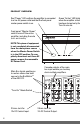
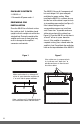
PRODUCT OVERVIEW Red “Power” LED confirms the amplifier is connected to a live AC power outlet and that the front panel master power switch is on. Green “Active” LED lights when the amplifier circuit has been turned on by the Turn-On circuits. Front panel “Master Power” switch turns off the entire amplifier, including the auto turn- on circuitry. NOTE:This piece of equipment is not completely disconnected from the main power source when the Master Power Switch is in the OFF position.
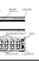
s try e Attractive extruded aluminum front panel. Red “protect” LED indicates a fault condition (D.C. output). Bridging switches, BusMatrix controls, dedicated inputs and level controls for each channel. 6 7 8 9 10 11 12 6 7 8 9 10 11 12 Dual banana spaced binding posts for speaker connections. Gold-plated RCA jacks Removable Two-prong 16 gauge 6’ AC power cord.
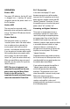
PACKAGE CONTENTS n A30-X12 x 1 n Removable AC power cord x 1 PREPARING FOR INSTALLATION Place the A30-X12 on a flat level surface like a table or shelf. It should be placed upright so that its weight rests on the four attached feet. Placing the weight of the amplifier on the rear or front panel may result in damage to the amplifier's connectors and controls. Figure 1 The A30-X12, like any hi-fi component, will last much longer if it is given adequate ventilation for proper cooling.
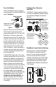
Bridging Two Channels into One Turn-On Modes The Turn-On Mode selector switch gives you three options for turning the A30-X12 on and off. See figure 5 The A30-X12's bridging switches allow you to create a more powerful amplifier channel by combining or "bridging" two adjacent channels. MODEL SI-1200 1 Niles Audio Corporation, Inc. MAIN Slide the switch with your BUS fingernail or a 1/8” slotted INPUT screwdriver blade.
Configuring Your System Because the A30-X12 offers so many configuration possibilities it is important to plan carefully before you install it. Draw a block diagram of your system and use the Configuration Worksheet on page 7 to record how you plan to connect your A30-X12. Here is an example filled out according to the block diagram on page 7. Mark the cables with Wire labels, describing where the cables originate from, rather than where they will terminate.
OPERATION D.C. Protection Power LED In the event a damaging D.C. signal becomes present on any of the speaker terminals, the D.C. protection circuit shuts down the entire amplifier and the red LED labeled “Protection” illuminates. To reset the amplifier you must turn the front panel power switch “off” and then “on.” The power LED indicates that the AC cord is plugged into a working AC power receptacle and that the power switch is in the "On" position.
TROUBLESHOOTING No sound on one channel BusMatrix DIP switch is not in the correct position. Check your configuration worksheet for the correct setting and verify. You could have a short circuit or loose wire at speaker or amplifier terminals. Check that connections are secure and that there are no loose strands of wire crossing from the positive to the negative terminal at the back of the amplifier and the speaker. Amp will not turn on AC power cord must be plugged into a working outlet.
CONFIGURATION WORKSHEET BUS INS & OUTS CONNECTED TO Left Main Bus Right Main Bus Cascade Output CH # BRIDGED DIP INPUT SOURCE SPEAKER 1 2 3 4 5 6 7 8 9 10 11 12 MODE SETTINGS IN USE SPECIAL CONNECTIONS OR NOTES Constant Audio Sense Voltage Trigger Control Output 9
SPECIFICATIONS Power handing: 30 watts x 12 Frequency response: 5 Hz to 50 kHz +/- 3dB Signal noise ratio: >= 85 dB Power supply AC120V, 60 Hz Power consumption 9 amps Dimensions: 17” wide x 5-1/2” high (including feet) x 15” deep Warranty: 2 year limited 10
LIMITED WARRANTY JobSite Systems (“JOBSITE”), a Niles Audio Corporation company, warrants its passive products (those not requiring AC or battery power) to the original purchaser to be free of manufacturing defects in material and workmanship for a period of ten years from date of purchase.
NOTES: 12
NOTES: 13
JOBSITE SYSTEMS 12331 S.W. 130 STREET, MIAMI, FLORIDA 33186 P 866.4JB.SITE (866.452.7483) – F 305.238.0185 WWW.JOBSITESYSTEMS.COM © 2004 JobSite Systems. All rights reserved. JobSite, Pure Custom and Niles are registered trademarks of Niles Audio Corporation and the JobSite Logo is a trademark of Niles Audio Corporation. All other trademarks are the property of their respective owners. Some JobSite products (or components thereof) are manufactured under one or more U.S.