System 9100 Technical Manual 636.
Configuration Guides—XT-9100 Configuration Guide
XT-9100 Extension Module/ XP-910x Expansion Modules Introduction The XT-9100 Extension Module and its expansion modules have been designed to provide additional input and output capacity within Metasys Networks and specifically for the DX-9100 Extended Digital Controller. The XT-9100 module provides the communication interface and the XP modules provide the analog and digital inputs and outputs. A Supervisory System communicates with an XT-9100 via the N2 Bus or Bus 91*.
Hardware Configuration For full details of the hardware configuration, refer to the XT-9100 Technical Bulletin (LIT-6364040).
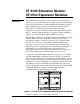
Bus Connector (provided) HOT GND RS485 NEUT EXP A B C A B C EXP C O M 24V TR EXP XP9102 FU S E C O M 24V XT A I5 A I6 V DO1 DO2 DO3 DO4 EXP DO1 DO2 DO3 DO4 DO5 DO6 DO7 DO8 max AO8 min RD TD XT9100 FUSE EXP +15V max AO7 min Power TR9100 AI1 AI2 AI3 AI4 ADDRESS XP9103 AO 7 AO8 C 24 V DO5 DO 6 DO 7 DO8 XP1 XP2 emtxt-4 Figure 2: Typical XT-9100 Configuration Table 2: XT Configurations TR Transformer TR-9100 XT Processor XT-9100 XP1 Analog XP-9102 (optional) (See
Configuration Guides—XT-9100 Configuration Guide
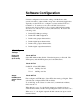
Software Configuration Software configuration involves the setting of all the Items of the extension module to values which correspond to the intended application. Typically, use the GX Tool to configure a system, and the SX Tool to troubleshoot. To use these tools, refer to the GX-9100 Software Configuration Tool for Windows User’s Guide (LIT-6364060) and the SX-9100 Service Module User’s Guide (LIT-6364070). Proceed in the following order: 1. Define XT-9100 type settings. 2.
Via the SX Tool The “Output Hold/Reset on Communication Failure” flag is set at Bit X2 of Item XTS (RI.69). Maximum Time Between Communications X2 = 0 Output reset upon communication failure X2 = 1 Output hold upon communication failure When communication fails for the period set in this Item, the XT-9100 goes into “communication failure” state, indicated by a blinking power LED on the front of the module. The default value is 60 seconds. Via the GX Tool First configure an XT Module.
XT-9100 Configuration Settings Via the GX Tool The I/O type and map details are automatically generated by the GX-9100 Graphic Configuration Software when all I/O data for extension modules has been entered. It is then downloaded into the XT-9100 directly or via the DX-9100 and XT-Bus. (Refer to the Download/Upload section, further in this document.) When in the GX Tool, select the XT module, then define it as Analog or Digital (if Digital, define it as 8 DI, 4DI/4DO, or 8DO). This defines Module XP1.
Note: The data base in the XT-9100 has been designed to accept most configuration of inputs and outputs. All inputs and outputs which are physically connected through expansion modules must be configured, and only those points. If there is a difference between the physical configuration and the software configuration, the XT-9100 will signal an error condition to the DX-9100 (XTnERR).
Via the SX Tool The input type for the eight possible inputs (n = 1 to 8) can be configured in Item AITn (RI.88, RI.96, RI.104, RI.112, RI.120, RI.128, RI.136, and RI.144). The unit of each analog input can be selected with following bits: (For RTD inputs, Celsius or Fahrenheit must be selected.) X4 X3 X2 X1 = 0000 No Units X4 X3 X2 X1 = 0001 Celsius X4 X3 X2 X1 = 0010 Fahrenheit X4 X3 X2 X1 = 0011 Percent Changing individual temperature units for each AI can only be done in the SX Tool.
AI Input Type: Alarm on Unfiltered Value An alarm from the High Limit (HIAn) and Low Limit Alarm (LOAn) will be generated from the unfiltered or filtered input. (See Filter Time Constant.) Via the GX Tool Select XTn, AIn, and Data. At the “Alarm Unfiltered” field, enter “0” for No (Alarm on Filtered Value), or “1” for Yes (Alarm on Unfiltered Value). Via the SX Tool Select Item AITn.
Via the SX Tool Input Type: X7 = 0 0-10 volts X7 = 1 0-20 mA X8 = 1 20% suppression 2-10V or 4-20 mA) Linearization and Sensor Type: X11 X10 X9 = 000 Linear (Active Sensor) X11 X10 X9 = 001 Ni 1000 RTD Passive Sensor (JCI Type) (-45 to +121°C/-50 to +250°F) X11 X10 X9 = 010 Ni 1000 RTD High Temperature Sensor (+21 to +288°C/70 to +550°F) X11 X10 X9 = 011 RTD Sensor A99 (-50 to +100°C/-58 to +212°F) X11 X10 X9 = 100 RTD Sensor Platinum 1000 (+50 to +200°C/-58 to +320°F) For active inputs, ea
Via the SX Tool The high limit is at Item HIAn (RI.91, RI.99, RI.107, RI.115, RI.123, RI.131, RI.139, and RI.147), the low limit is at Item LOAn (RI.92, RI.100, RI.108, RI.116, RI.124, RI.132, RI.140, and RI.148). These Items may also be set by a Supervisory System and will always be set by a DX-9100 Controller. The differential on alarm limits is adjustable with Item ADFn (RI.93, RI.101, RI.109, RI.117, RI.125, RI.133, RI.141, and RI.149).
Digital Input Configuration An XT-9100 can accept up to 16 digital inputs, which will be considered active when driven to a common digital ground. The first eight digital inputs are connected to XP1 and the next eight digital inputs to XP2. Each digital input is defined and configured by the following parameters: • Tag name (optional, GX-9100 only) • Input type • Counter prescaler Inputs may be defined as maintained or pulse type.
DI: Counter Prescaler The digital input transitions of XP1 are counted as follows: Digital Input DIn Prescale PCn (RI.09) (RI.48-55) Count Transition Pulse Counter CNTRn (RI.32-39) emcmxt-3 Figure 3: Counter Prescaler A count transition occurs when the number of positive transitions of the digital input (DIn) equals the value of the prescaler (PCn). The Pulse Counter (CNTn) counts the count transitions (n = 1-8). Note: Counters are only available in the XP1 location.
AO: Output Type Via the GX Tool Select XTn, ANALOG, XTn, AOn, and Data, then enter the output code: 0 = disabled 1 = 0 to 10 VDC 2 = 0 to 20 mA 3 = 4 to 20 mA Via the SX Tool The output type can be configured in Item AOT (RI.87) in bit pairs X2 X1, X4 X3, ...X16 X15 for Outputs 1-8).
AO: Source (with DX-9100 Only) The source of the analog output signal is defined in the DX-9100 Controller. Via the GX Tool Select XTn, AOn, Data, and the “Source Point” field. Enter * and select the required source variable. Via the SX Tool Refer to the Extension Module Configuration section of the DX-9100 Configuration Guide (LIT-6364030). AO Notes 1. When the XT-9100 is connected to a DX-9100 Controller, you can view and override the AO value from the DX-9100 front panel.
Digital Output Configuration Each digital output is defined and configured by the following parameters: • Tag name (GX-9100 only) • Output type • Pulse time When the XT is connected to a DX-9100 Controller, the following parameter is defined in the DX-9100 for the digital output: • DO: Type of Output Source Via the GX Tool Select XTn (or EXP) and DOn, then select either of the On/Off or Pulse fields.
DO Source (with DX-9100 Only) The source of the digital output signal is defined in the DX-9100 Controller. Via the GX Tool Select XTn or (EXP), DOn, Data, and then the “Source Point” field. Enter * and select the required source variable. Via the SX Tool Refer to the Extension Module Configuration section in the DX-9100 Configuration Guide (LIT-6364030). DO Notes 1. When the XT-9100 is connected to a DX-9100 Controller, you can view and override the DO value from the DX-9100 front panel.
Download/ Upload Via the GX Tool Download via DX-9100 Controller and N2 Bus Connect an RS-232-C/RS-485 converter (type MM-CVT101-x in North America and type IU-9100-810x in Europe) to one of the serial communication ports (COM1 or COM2) of the personal computer on which the GX Tool is running. Connect the N2 Bus of the DX-9100 to the converter unit connected to the PC.
Upload via a DX-9100 Controller Only complete DX-9100/XT-9100 configurations should be uploaded from the DX-9100. Select DX-9100 and NEW to clear the PC screen. Select DX-9100, UPLOAD, and DX&XT. Enter the DX-9100 Controller address (0-255) and PC port (1 or 2). Press . Download via the N2 Bus Set the address switches and jumpers on the XT/XP devices as required. Connect the XT/XP devices to the N2 Bus and the N2 Bus to the converter on the PC.
Appendix 1: SX Tool Item Description and Tables The following information is important when commissioning with the SX Service Module. General Each constant, variable, or value in an XT-9100 Extension Module can be addressed via an Item code. All Items are contained in the Item List. Note: It is important to note that EEPROM Items can only be written approximately 10,000 times, so that write commands from cyclical processes in Supervisory Systems must be avoided.
3. Totalized Numerical Items are actual positive numbers. They refer to totalized values of pulse counters. They are displayed and entered as whole numbers, without a sign or decimal point. These Items are shown in the Item List with “4 Bytes” in the Type column. 4. Status Items are either 1-byte or 2-byte Items giving information on the actual status or configuration of the inputs, outputs and modules, where each bit has a specific meaning as described in the Item List.
Floating Point Numbers A DX-9100 floating point number consists of two bytes with following format: 15 14 13 12 11 10 E3 E2 E1 E0 9 8 7 6 5 4 3 2 1 0 S M10 M9 M8 M7 M6 M5 M4 M3 M2 M1 M0 where: EEEE S = 4 bits exponent = sign (1=negative) MMMMMMMMMMM = 11 bits mantissa Note: 216 = 32,768; subtracting 4 bits for the exponent, 1 bit for the sign, and 11 bits for the mantissa leaves a maximum value of 2047 for most numeric entries with single digit resolution.
Table 3: Item List RI. HI. Type R/W Tag Description 00 00 1 Byte R MODL Device Model : 08H 01 01 1 Bytes R/W OPMO Operation Mode (status) X8 X7 X6 X5 X4 X3 X2 X1 02 02 X1 = 1 Watchdog text X2 = DO Error X3 = DI Error X4 = AI Error X5 = AO Error X6 = Not Used X7 = FAIL XT Fail Mode (= XTS, bit X2) X8 = 1 PWR Power Fail or Comm.
RI. HI.
RI. HI.
RI. HI.
RI. HI.
RI. HI.
RI. HI.
RI. HI.
RI. HI.
RI. HI.
RI. HI.
RI. HI.
Notes 38 Configuration Guides—XT-9100 Configuration Guide
Notes Configuration Guides—XT-9100 Configuration Guide 39
Notes Controls Group 507 E. Michigan Street P.O. Box 423 Milwaukee, WI 53201 40 Configuration Guides—XT-9100 Configuration Guide FAN 636.4 System 9100 Technical Manual Printed in U.S.A.