
Inc. Extension Module/ Expansion Module Configuration Guide


10 Configuration Guides—XT-9100 Configuration Guide
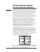
Note: The data base in the XT-9100 has been designed to accept most
configuration of inputs and outputs. All inputs and outputs
which are physically connected through expansion modules
must be configured, and only those points. If there is a
difference between the physical configuration and the software
configuration, the XT-9100 will signal an error condition to the
DX-9100 (XTnERR).
Each analog input is defined and configured by the following parameters:
• Tag name (optional, GX-only)
• Measurement units (for RTD inputs)
• Enable square root
• Alarm on unfiltered value
• Input signal range
• Alarm limits
• Filter time constant
The GX Tool determines the input signal range with a 2-stage process:
you must first decide if the input is active or passive; the remaining
options depend on this choice. With the SX Tool, this information is
entered into a number of Items.
Via the GX Tool
Select XTn, AIn, then either Active or Passive.
Note: All AI points must be configured even if not connected to a sensor
to enable the generation of a complete IO Map and to ensure
correct operation with the DX-9100 Controller.
Via the GX Tool
The selection of Celsius or Fahrenheit, is set in the Global data of the
DX-9100 (select DX-9100, then Global. At the “Temperature Units”
field, enter “C” for Celsius or “F” for Fahrenheit).
To determine the measurement units of active inputs, select XTn, AIn,
Data, and then enter in the “Measurement Units” field:
0 = None
1 = Temperature (“C” or “F” as entered in Global)
2 = Percent (%)
Note: The units of an active input are not read by the DX-9100
Controller, but are available to any other Supervisory System
which may be connected.
Analog Input
Configuration
AI Input Type:
Measurement
Units