
Inc. Extension Module/ Expansion Module Configuration Guide


Configuration Guides—XT-9100 Configuration Guide 17
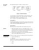
Via the GX Tool
Select XTn, ANALOG, XTn, AOn, and Data, then enter the output code:
0 = disabled
1 = 0 to 10 VDC
2 = 0 to 20 mA
3 = 4 to 20 mA
Via the SX Tool
The output type can be configured in Item AOT (RI.87) in bit pairs
X2 X1, X4 X3, ...X16 X15 for Outputs 1-8). To define the output signal
set the bits (for Output 7, for example) as follows:
X14 X13 = 00 Output Disabled
X14 X13 = 01 Output 0-10V
X14 X13 = 10 Output 0-20 mA
X14 X13 = 11 Output 4-20 mA
The AO range of the analog output is defined in the DX-9100 Controller.
The High Range defines the level of control source signal that corresponds
to an output of 100%.
The Low Range defines the level of control source signal that corresponds
to an output of 0%.
When the source point is equal to the high range, then the output will be at
the maximum signal (10V/20 mA). When the source point is equal to low
range, then the output will be at the minimum signal (0V, 0/4 mA).
Via the GX Tool
Select XTn, AOn, and Data, then enter the desired values in the “High
Range” and “Low Range” fields.
Via the SX Tool
Refer to the Extension Module Configuration section of the DX-9100
Configuration Guide (LIT-6364030).
AO: Output Type
AO: Range
(with DX-9100
only)