
Operation Manual


10
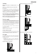
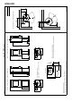
Fig. 1c
Jøtul F 130 Series
**900
X
Y
900196-P01
1098
433
952
1098
433
952
396
410
410
396
190
190
*123
*123
108
108
(2)
(2)
(2)
(2)
(2)
(2)
(1)
(1)
(1)
(1)
(1)
(1)
180
405
*358
***400
400
605
***605
100
*223
290
***180
***100
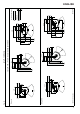
Jøtul F 135 (with base and sideglasses)
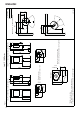
(1) -
Flue pipe center
(2) -
Outside air connection center
Floor plate
* Outside air connection
** Min. distance to furniture / combustible material
***
Distance to combustible wall with semi-insulated / shielded flue pipe
Radiation
zone
Jøtul F 137 (with pedestal and sideglasses)
Min. measurements floor plate
X / Y= According to national laws and regulations
Min. distance to combustible wall
Combustible wall
ENGLISH