
Operation Manual


5
300
903
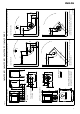
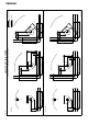
Fig. 1a
Jøtul F 162 C / Jøtul F 163 C
Jøtul F 162 / Jøtul F 163
Hole in wall for external air
Ø 100 mm
Hole in floor for external
air Ø 100 mm
Combustible wall
Min. measurements floor plate X,Y =
According to national standards
and regulations. See chapter 4.1
* With semi-insulated chimney / covered flue pipe down
towards the product.
** Jøtul F 162 C / F 163 C with semi-insulated chimney /
covered flue pipe down towards the product.
900061-P08
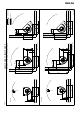
Jøtul F 162 C / F 163 C
Min. distance to combustible wall, convection model
Jøtul F 162 / F 163
Min. distance to combustible wall, base model
Jøtul F 162 / Jøtul F 163 / Jøtul F 162 C / Jøtul F 163 C
825
600
1000
200
*150
412
*362
647
*592
200
**150
584
**513
972
*831
1207
*1066
819
**748
413
**363
687
*587
500
*400
Y
X
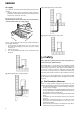
948
648
300
235
93
475
473
147
235
93
450
447
119
100
789
603
537
***437
***200
*** for F 162 C only
300
100
**50
340
**290
575
**525
1000
ENGLISH