www.sainsmart.com Arduino Introduction Overview What is Arduino? Arduino is a tool for making computers that can sense and control more of the physical world than your desktop computer. It's an open-source physical computing platform based on a simple microcontroller board, and a development environment for writing software for the board.
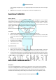
www.sainsmart.com 2. supply voltage through this pin, or, if supplying voltage via the power jack, access it through this pin. AREF. Reference voltage for the analog inputs. Used with analogReference(). SainSmart UNO R3 What’s UNO R3? The Arduino Uno is a microcontroller board based on the ATmega328. It has 14 digital input/output pins (of which 6 can be used as PWM outputs), 6 analog inputs, a 16 MHz ceramic resonator, a USB connection, a power jack, an ICSP header, and a reset button.
www.sainsmart.com joystick, etc. The MEGA2560 R3 also adds SDA and SCL pins next to the AREF. In addition, there are two new pins placed near the RESET pin. One is the IOREF that allow the shields to adapt to the voltage provided from the board. The other is a not connected and is reserved for future purposes. The MEGA2560 R3 works with all existing shields but can adapt to new shields which use these additional pins.
www.sainsmart.com Arduino C Grammar Arduino grammar is built on the basis of C/C + +, in fact is also the basic C grammar, Arduino grammar not only put some related parameters Settings are function change, we have no need to understand his bottom, let us to know AVR micro control unit (MCU) friend can also easy to fit in. So here I'll simple comment the Arduino grammar. Control Structures If if...else for switch case while do...
www.sainsmart.com >= && || ! Data type boolean char byte int unsigned int long unsigned long float double string array void Constant HIGH | LOW Said digital IO port level, HIGH Said high level(1), LOW Said low electric flat(0). INPUT | OUTPUT Said digital IO port direction, INPUT Said input (high impedance state) OUTPUT Said output (AVR can provide 5 v voltage and ma current). TURE | FALSE true(1) , false(0).
www.sainsmart.com Analog I/O int analogRead(pin) pin 0~5. analogWrite(pin, value) pin 3, 5, 6, 9, 10, 11, value is 0 to 255 Time delay(ms)Pauses the program for the amount of time (in miliseconds) specified as parameter. (There are 1000 milliseconds in a second.)(unit ms).
www.sainsmart.com Chapter 1 Hello World! In this chapter, we will learn use Arduino IDE serial interface tools to show the contents that we want to display in the computer. Example code: void setup() { Serial.begin(9600);// opens serial port, sets data rate to 9600 bps Serial.println("Hello World!"); } void loop() { } Explain: Serial.begin(9600); The comment says 9600 bps, and just so you know bps stands for bits-per-second (we will refer to this as the baud rate).
www.sainsmart.
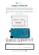
www.sainsmart.com Chapter 2 Blink LED Small LED lamp experiment is the basis of comparison of the experimental one, this time we use the motherboard comes with 13 feet of LED lights to complete the experiment, the experimental equipment we need is the Arduino which each experiment must have and USB download cable. Next we connect small lamp in accordance with the following experimental schematic physical map.
www.sainsmart.com void loop() { digitalWrite(ledPin, HIGH); //light up led lamp delay(1000) ; //delay 1s digitalWrite(ledPin, LOW) ; //go out led lamp delay(1000) ; // delay 1s } After downloading the program, you can see our 13-foot LED lights flashing, so that our small lights flicker experiment is complete.
www.sainsmart.com Chapter3 LED Blink light emitting diode What’s light emitting diode? The light emitting diode referred to as LED. By gallium (Ga) and arsenic (AS) and phosphorus (P) made of a compound of the diode, when the electron and hole recombination can radiate visible light, and thus can be used to prepare a light-emitting diode in the circuit and the instrument as the indicator, or the composition of the text or digital display.
www.sainsmart.com Example code: int ledPin=8; //set IO pin of LED in control void setup() { pinMode(ledPin,OUTPUT);//set digital pin IO is OUTPUT } void loop() { digitalWrite(ledPin,HIGH); //set PIN8 is HIGH , about 5V delay(1000); //delay 1000ms, 1000ms = 1s digitalWrite(ledPin,LOW); //set PIN8 is LOW, 0V delay(1000); //delay 1000ms, 1000ms = 1s } setup() The setup() function is called when a sketch starts. Use it to initialize variables, pin modes, start using libraries, etc.
www.sainsmart.com Arduino board. loop() After creating a setup() function, which initializes and sets the initial values, the loop() function does precisely what its name suggests, and loops consecutively, allowing your program to change and respond. Use it to actively control the Arduino board.
www.sainsmart.com Chapter4 PWM What’s PWM? Pulse Width Modulation, or PWM, is a technique for getting analog results with digital means. Digital control is used to create a square wave, a signal switched between on and off. This on-off pattern can simulate voltages in between full on (5 Volts) and off (0 Volts) by changing the portion of the time the signal spends on versus the time that the signal spends off. The duration of "on time" is called the pulse width.
www.sainsmart.com running at Vcc = 5 volts. In that case, a value of 255 will also be 5 volts. We can then easily convert the desired voltage to the digital value needed using simple division. We first divide the voltage we want by the 5 volts maximum. That gives us the percentage of our PWM signal. We then multiply this percentage by 255 to give us our pin value.
www.sainsmart.com Example code: int brightness = 0; int fadeAmount = 5; change. //define original value of brightness, the value is brightness of LED.
www.sainsmart.com Chapter5 Advertising LED Experiment component: LED lamp: 6 220Ω resistors: 6 Breadboard & Jumper wires Connect your circuit as the below diagram.
www.sainsmart.com Example code Program code is in the advertising lights program folder. Double-click to open and you will see a led2 folder, open it, you will find out a led2.pde file. Double-click the icon to open it. Then you will see that it is the arduino programming software window with the experimental program code.
www.sainsmart.
www.sainsmart.
www.sainsmart.com pinMode(i,OUTPUT);//set i pin output The “for” statement is used to repeat a block of statements enclosed in curly braces. An increment counter is usually used to increment and terminate the loop. The for statement is useful for any repetitive operation, and is often used in combination with arrays to operate on collections of data/pins.
www.sainsmart.com Chapter6 Traffic light Experiment component: Red , Green , Yellow led lamp: 3 220Ω resistor: 3 Breadboard & Jumper wires Connect your circuit as the below diagram. Example code: Program code is in the traffic lights program folder. Double-click to open and you will find out a trafficLed.pde file. Double-click the icon to open it. Then you will see that it is the arduino programming software window with the experimental program code.
www.sainsmart.
www.sainsmart.com Chapter7 Buzzer What’s buzzer? The buzzer is one integrated electronic transducers, DC voltage supply, widely used in computers, printers, copiers, alarm, electronic toys, automotive electronic equipment, telephones, timers and other electronic products for sound devices. They can be divided into the: active buzzer (containing driver line) and passive buzzer (external drive) in their drive different way, teach you to distinguish between active buzzer and passive buzzer.
www.sainsmart.com of 8 mm. As facing up to two buzzers’ pin County it can be seen that there are a green circuit board is passive buzzer, no circuit board using vinyl enclosed one is active buzzer.
www.sainsmart.com Experiment component: Buzzer : 1 Breadboard & Jumper wires Connect your circuit as the below diagram.
www.sainsmart.com { digitalWrite(buzzer,HIGH);//sound delay(1);//delay 1ms digitalWrite(buzzer,LOW);//mute delay(1);//delay 1ms } for(i=0;i<100;i++)// Output the other frequency of sound { digitalWrite(buzzer,HIGH);//sound delay(2);//delay 2ms digitalWrite(buzzer,LOW);//mute delay(2);//delay 2ms } } } while loops Description while loops will loop continuously, and infinitely, until the expression inside the parenthesis, () becomes false.
www.sainsmart.com Chapter8 Tilt switch What’s Tilt Sensor? The tilt sensor is a component that can detect the tilting of an object. However it is only the equivalent to a pushbutton activated through a different physical mechanism. This type of sensor is the environmental-friendly version of a mercury-switch. It contains a metallic ball inside that will commute the two pins of the device from on to off and viceversa if the sensor reaches a certain angle.
www.sainsmart.
www.sainsmart.com { pinMode(8,OUTPUT);//set pin8 output } void loop() { int i;//define i while(1) { i=analogRead(5);//read voltage values of pin5 if(i>200)//if more than 512(2.
www.sainsmart.com Chapter9 Potentiometer What’s Analog Pins? 1. A/D converter The Atmega168 contains an onboard 6 channel analog-to-digital (A/D) converter. The converter has 10 bit resolution, returning integers from 0 to 1023. While the main function of the analog pins for most Arduino users is to read analog sensors, the analog pins also have all the functionality of general purpose input/output (GPIO) pins (the same as digital pins 0 - 13).
www.sainsmart.com It takes about 100 microseconds (0.0001 s) to read an analog input, so the maximum reading rate is about 10,000 times a second. Syntax analogRead(pin) Parameters pin: the number of the analog input pin to read from (0 to 5 on most boards, 0 to 7 on the Mini and Nano, 0 to 15 on the Mega) Returns int (0 to 1023) What’s Potentiometer? A potentiometer is a simple knob that provides a variable resistance, which we can read into the Arduino board as an analog value.
www.sainsmart.com int potpin = 0 ; //define analog pin0 int ledpin = 13 ; //define analog pin13 int val = 0 ; //set val is0. void setup() { pinMode(ledpin,OUTPUT);//set analog pin13 output Serial.begin(9600);//set baud rate 9600 } void loop() { digitalWrite(ledpin,HIGH);//light up led in pin13 delay(50);//delay 0.05s digitalWrite(ledpin,LOW);//go out led in pin13 delay(50);//delay 0.05s val = analogRead(potpin);//give the value of pin0 to val Serial.
www.sainsmart.com Chapter10 Photoresistor What’s photoresistor? Photoresistor, also known as light pipes, common production materials is cadmium sulfide, There are also selenium, aluminum sulfide, lead sulfide and bismuth sulfide material. these production materials having characteristics in light of a specific wavelength, its resistance decreases rapidly.
www.sainsmart.com Example code: int photocellPin = 2; //define photocellsh=2, read the value of voltage. int ledPin = 12; //define ledPin12 is the output port of led’s level. int val = 0; //define original of val. void setup() { pinMode(ledPin, OUTPUT); //set ledPin output } void loop() { val = analogRead(photocellPin); //get the value from sensor if(val<=512){ //512=2.5V, if want the sensor be more sensitive, increase the number, or lese low the number.
www.sainsmart.com digitalWrite(ledPin, HIGH); //when the value of val is less than 512(2.
www.sainsmart.com Chapter11 LM35 temperature sensor Temperature sensor What’s temperature sensor? The temperature sensor is that use substances of various physical properties with temperature variation of the sensor and let the temperature converted to electricity. These regularly change the physical properties of the main body temperature sensor is a core part of the temperature measuring instruments, and a wide variety.
www.sainsmart.com Out can be seen from experimental cartridge of the temperature sensor, temperature sensor side is flat, and the other side is semicircular. Flat face of our own, the leftmost VCC pin (connected to +5 v), the middle of the GND pin VOUT (voltage value output pin, then the analog pins on the board), and the rightmost pin (connected board GND). Three pins, respectively, then you can use.
www.sainsmart.com { Serial.begin(9600); } void loop() { int val; int dat; val = analogRead(potPin); dat = (125*val)>>8 ; // Temperature calculation formula Serial.print("Tep : ") ; //print “Tep” means temperature Serial.print(dat) ; // print the value of dat Serial.println("C"); //print “C” means degree delay(500);//delay 0.5s } Program function Download the program to the experimental board, open the monitor, you can see the current ambient temperature.
www.sainsmart.com Chapter12 Nixie tube Experiment component digital tube x1 220 Ω resistance x4 Breadboard & jumper wire Connect your circuit as the below diagram.
www.sainsmart.
www.sainsmart.
www.sainsmart.
www.sainsmart.com Chapter13 4-bit Nixie tube What’s digital tube? Digital tube is one kind semiconductor light emitting device. Their basic unit is light emitting diode. Digital tube is divided into 7 segment digital tube and 8 digital tube by the number of segments, 8 digital tube has one more light-emitting diode unit (a decimal point display) than 7 segment digital tube; Digital tube has be divided into 1, 2, 4, and so on digital tube depend on how many “8” it can show.
www.sainsmart.com Working principle Each segment of the digital tube is make up of the light emitting diode, and so when used with the light emitting diode, it should connect with the current-limiting resistor as well, if not the excessive current may burn light emitting diode. The digital tube used in this experiment is a common anode common anode, The public pole COM received +5 V when the common anode Digital tube be applied.
www.sainsmart.com Digital tube display number Experiment component 4-bit digital tube x1 220 Ω resistance x4 Breadboard & jumper wire Connection Driven digital tube current limiting resistor is certainly indispensable, there are 2 ways of limiting resistor connection. The first one is connected with D1-d4 anode, totally connect four. This connection method’s benefit is needs of relatively less resistance, but generates different the digital brightness. The brightest is 1, 8 is the darkest.
www.sainsmart.com Refer to figure below wiring for the 5643S Example code This is a simple stopwatch. Its accuracy is not very high. You need to fine-tune the parameters.
www.sainsmart.
www.sainsmart.
www.sainsmart.
www.sainsmart.
www.sainsmart.
www.sainsmart.
www.sainsmart.com Chapter14 74HC595 What’s 74HC595? 74HC595 with 8-bit register and a memory, and has three-state output function. we use it to control 8 LED lights. Why do we choose 74HC595? If we control eight small lights just with Arduino, how many its I / O will be occupied? The answer is eight. However one arduino uno only have 20 I/O port. 8 small lights have take up too many resources. The purpose we use 74HC595 is to reduce the occupation of the number of I / O port.
www.sainsmart.com This schematic seems are complex,after analysis and combined with reference we will find it very simple.
www.sainsmart.
www.sainsmart.
www.sainsmart.com Result We will see small red lights and green lights flashing take turns. This is the end of this chapter’s experiment, we hope that you could enjoy it and create more interactive works.
www.sainsmart.
www.sainsmart.
www.sainsmart.
www.sainsmart.com The code in the folder - "8x8 the matrix LEDs experimental", can be used as a reference, made more exciting experiments.
www.sainsmart.com Chapter16 Infrared remote control Infrared receiving head What’s Infrared receiving head? Infrared remote control signals sent a series of binary pulse code. In order to make it from other infrared signal interference during wireless transmission, typically modulated it on a particular carrier frequency, and then emitted it by the infrared-emitting diode.
www.sainsmart.com Infrared remote control experiment Experiment component 1. IR remote control x1 2. 3. 4. 5. Infrared receiving head x1 Buzzer x1 220 Ω resistance x1 Breadboard & jumper wires Experiment principle If you want to decode remote control, you must understand the coding system of the remote controller first. The coding system of the remote control we used is NEC protocol. Now let’s learn about NEC protocol: NEC protocol introduction: Feature: (1)8-bit address spaces, 8-bit command spaces.
www.sainsmart.com in the received message recognized. The total transmission time is constant, because the duplication of every point of its length negated. If you're not interested, you can ignore this reliability negated address and command can also expand to 16! According to the characteristics and the receiving end of the waveform of the NEC coding, this experiment will divided receiving end’s wave form into four parts: Primer searching code (9ms And 4.
www.sainsmart.
www.sainsmart.
www.sainsmart.com { while(digitalRead(IR_IN));//if high wait Pulse_Width=TCNT1; TCNT1=0; if(Pulse_Width>=68&&Pulse_Width<=72)// 4.5ms { pulse_deal(); return; } else if(Pulse_Width>=34&&Pulse_Width<=36)//2.25ms { while(!(digitalRead(IR_IN)));// if low wait Pulse_Width=TCNT1; TCNT1=0; if(Pulse_Width>=7&&Pulse_Width<=10)// 560us { return; } } } } void setup() { Serial.begin(9600); pinMode(IR_IN,INPUT);// Set infrared receiving pin for input Serial.
www.sainsmart.
www.sainsmart.com Chapter17 1602LCD What’s 1602LCD? Nowadays 1602LCD is application of very wide range. The initial 1602 LCD used HD44780 controller. But now various manufacturers basically adopt compatible IC with their 1602 module. Their characteristics are basically the same. 1602LCD Display capacity: 16x2 characters; Chip operating voltage: 4.5V~5.5V; Operating current: 2.0mA(5.0V); Best operating voltage: 5.0V; Character size: 2.95x4.35( WxH ) mm.
www.sainsmart.com 2. VL is used to adjust the contrast. It connected in series the potentiometer is not greater than a 5KΩ. This experimental used one 1KΩ of resistor to set contrast. There are high potential connection and low potential connection. It connected in series 1KΩ resistance then connected to GND.
www.sainsmart.com Additionally, wire a 10K pot to +5V and GND, with it's wiper (output) to LCD screens VO pin (pin3). Example code // include the library code: #include
www.sainsmart.com // initialize the library with the numbers of the interface pins LiquidCrystal lcd(12, 11, 5, 4, 3, 2); void setup() { // set up the LCD's number of columns and rows: lcd.begin(16, 2); // Print a message to the LCD. lcd.print("hello, world!"); } void loop() { // set the cursor to column 0, line 1 // (note: line 1 is the second row, since counting begins with 0): lcd.setCursor(0, 1); // print the number of seconds since reset: lcd.
www.sainsmart.com Chapter18 Relay module What’s relay? It will be able to control various appliances, and other equipments with large current. It can be controlled directly by Micro-controller (Arduino , 8051, AVR, PIC, DSP, ARM, ARM, MSP430, TTL logic) . This project will use 5V 2-Channel Relay interface board.
www.sainsmart.com int jdqPin=13; void setup() { pinMode(jdqPin,OUTPUT); Serial.begin(9600); } void loop() { digitalWrite(jdqPin,HIGH); delay(1000); digitalWrite(jdqPin,LOW); delay(1000); } Here I introduce how to use multimeter test relay pin. General relay has housing mark. If not, is also very simple test with a multimeter: 5V power supply Multimeter 1. 2. Find the coil pins Use multimeter to measure the resistance between the pins.
www.sainsmart.com Chapter19 Distance sensor Product features: Ultrasonic ranging module HC - SR04 provides 2cm - 400cm non-contact measurement function, the ranging accuracy can reach to 3mm. The modules includes ultrasonic transmitters, receiver and control circuit. The basic principle of work: Using IO trigger for at least 10us high level signal, The Module automatically sends eight 40 kHz and detect whether there is a pulse signal back.
www.sainsmart.com 0V Ground If you are sourcing a ultrasonic ranging module , the HC-SR04 is good choose . Its stable performance and high ranging accuracy make it a popular module in electronic market . Compared to the Shap IR ranging module , HC-SR04 is more inexpensive than it . But it has the same ranging accuracy and longer ranging distance. Specifications: power supply :5V DC quiescent current : <2mA effectual angle: <15° ranging distance : 2cm – 500 cm resolution : 0.
www.sainsmart.com Example code const int TrigPin = 2; const int EchoPin = 3; float cm; void setup() { Serial.begin(9600); pinMode(TrigPin, OUTPUT); pinMode(EchoPin, INPUT); } void loop() { digitalWrite(TrigPin, LOW); //Low-high-low level sent a short time pulse to TrigPin delayMicroseconds(2); digitalWrite(TrigPin, HIGH); delayMicroseconds(10); digitalWrite(TrigPin, LOW); cm = pulseIn(EchoPin, HIGH) / 58.0; //Echo time converted into cm cm = (int(cm * 100.0)) / 100.0; // retain two decimal places Serial.
www.sainsmart.
www.sainsmart.com Chapter20 Servo Motor Controlling a servo motor with an Arduino or other type of microcontroller is probably the easiest way to get started in robotics, motion art, or any other reason you may have to make your electronic project interact with the real world. Servos are very simple to interact with and in this post I’ll show you how to connect one to an Arduino.
www.sainsmart.com to its corresponding angle. Some servos will turn more or less than 180 degrees, so you may need to experiment. Programming: The Arduino software comes with a sample servo sketch and servo library that will get you up and running quickly. Simply load it from the menu as shown below. Their example uses pin 9 for the pulse wire, so to keep it simple, that’s what I used. You could use any of the data pins and, if you add more than one servo, you will need to.
www.sainsmart.com pin to use as the output. This line tells it to move from 0 degrees to 180 degrees one degree at a time: for(pos = 0; pos < 180; pos += 1) And this line tells it to move back to 0 degrees one degree at a time.
www.sainsmart.com Chapter21 XBee shield What’s XBee shield? The Arduino XBee shield (an Expansion Board without XBee module) is a compliant solution designed to meet low-cost, low-power wireless sensor networks with special needs. The module is easy to use, low power consumption, and the provision of critical data between devices reliable transmission. As the innovative design, XBee-PRO can be in the range 2-3 times beyond the standard ZigBee modules. XBee-PRO modules work in the ISM 2.
www.sainsmart.com To upload a sketch to an SainSmart board with a XBee shield, you'll need to put both jumpers on the shield to the "USB" setting (i.e. place them on the two pins closest to the edge of the board) or remove them completely (but be sure not to lose them!). Then, you can upload a sketch normally from the SainSmart environment. In this case, upload the Communication | Physical Pixel sketch to one of the boards.
www.sainsmart.com modules on its network and channel will receive the data it transmits. This can happen in a few ways: If a module's DH is 0 and its DL is less than 0xFFFF (i.e. 16 bits), data transmitted by that module will be received by any module whose 16-bit address MY parameter equals DL. If DH is 0 and DL equals 0xFFFF, the module's transmissions will be received by all modules.
www.sainsmart.com Send Command Expected Response ATWR OK To reset the module to the factory settings, use the ATRE command: Send Command Expected Response ATRE OK Note that like the other commands, the reset will not be permanent unless you follow it with the ATWR command. Here are some of the more useful parameters for configuring your XBee module. Command Description Valid Values Default Value ID The network ID of the XBee module.
www.sainsmart.com WR Write newly configured parameter values to non-volatile (long-term) storage. Otherwise, they will only last until the module loses power. CN Exit command mode now. (If you don't send any commands to the module for a few seconds, command mode will timeout and exit even without a CN command.) API mode As an alternative to Transparent Operation, API (Application Programming Interface) Operations are available.
www.sainsmart.com The 16-bit PAN ID is used in all data transmissions. The 64-bit PAN ID is used during joining, and to resolve 16-bit PAN ID conflicts that may occur. ZigBee defines three different device types: coordinator, router, and end devices. Coordinator Selects a channel and PAN ID (both 64-bit and 16-bit) to start the network Can allow routers and end devices to join the network Can assist in routing data Cannot sleep--should be mains powered.
www.sainsmart.com Chapter22 MPU6050 Sensor What’s MPU6050 Sensor? Description Key Features Model: GY-521 Color: Blue Material: PCB + Plastic + copper Chip: MPU-6050 Power supply: 3~5V Communication mode: standard IIC communication protocol Chip built-in 16bit AD converter, 16bit data output Gyroscopes range: +/- 250 500 1000 2000 degree/sec Acceleration range: +/- 2g, +/- 4g, +/- 8g, +/- 16g Immersion Gold plating PCB, machine welding process to ensure quality Pin pitch: 2.
www.sainsmart.com Packing list: 1 x Module 2 x Pins Specification sDimensions (cm): 2.1 x 1.6 x 0.3 Weight (kg): 0.005 If you need more information about MPU6050, visit: http://www.sainsmart.com/sainsmart-mpu-6050-3-axis-gyroscope-module.html Example code This code is without the algorithm, so the result is just raw data! // Arduino Wire library is required if I2Cdev I2CDEV_ARDUINO_WIRE implementation // is used in I2Cdev.h #include "Wire.
www.sainsmart.com accelgyro.initialize(); // verify connection Serial.println("Testing device connections..."); Serial.println(accelgyro.testConnection() ? "MPU6050 connection successful" : "MPU6050 connection failed"); // configure Arduino LED for pinMode(LED_PIN, OUTPUT); } void loop() { // read raw accel/gyro measurements from device accelgyro.getMotion6(&ax, &ay, &az, &gx, &gy, &gz); // these methods (and a few others) are also available //accelgyro.getAcceleration(&ax, &ay, &az); //accelgyro.
www.sainsmart.com bool blinkState = false; void setup() { Wire.begin(); Serial.begin(38400); accelgyro.initialize(); } void loop() { accelgyro.getMotion6(&ax, &ay, &az, &gx, &gy, &gz); Serial.print("a/g:\t"); Serial.print(ax/16384); Serial.print("\t"); Serial.print(ay/16384); Serial.print("\t"); Serial.print(az/16384); Serial.print("\t"); Serial.print(gx/131); Serial.print("\t"); Serial.print(gy/131); Serial.print("\t"); Serial.
www.sainsmart.com Chapter23 Keypad What’s keypad? Feature. 8P DuPont head, pitch 2.54mm, can be inserted in the Pin connection circuit; Peel off the white sticker on the back of the keyboard can be securely affixed to the surface of the chassis Experiment component Relay : 1 LED: 2 UNO R3: 1 Keypad : 1 Breadboard & Jumper wires USB cable: 1 Wiring Wiring up the parts is easier than it might seam. Note that D0 and D1 are used for serial programing.
www.sainsmart.
www.sainsmart.
www.sainsmart.com const byte ROWS = 4; const byte COLS = 4; char keys[ROWS][COLS] = {{'1','2','3','A'},{'4','5','6','B'},{'7','8','9','C'},{'*','0','#','D'}}; byte rowPins[ROWS] = {13, 12, 11, 10}; byte colPins[COLS] = {9, 8, 7, 6}; Keypad keypad = Keypad( makeKeymap(keys), rowPins, colPins, ROWS, COLS ); Password password = Password("0000"); void setup(){ Serial.
www.sainsmart.com passinput = 1; if(key == '*'){ password.reset(); passinput = 0; locked = 1; digitalWrite(relay1, HIGH); digitalWrite(relay2, HIGH); digitalWrite(relay3, HIGH); digitalWrite(relay4, HIGH); } if(password.evaluate()) { locked = !locked; password.